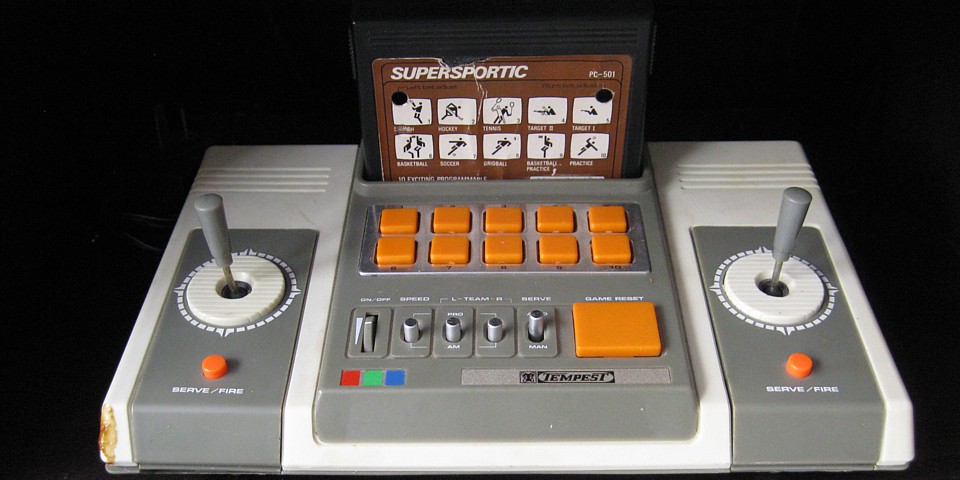
Tempest Programmable TV Game, model SD-050
The Tempest Programmable TV Game is one example of the PC-50x family of TV game consoles produced during the latter part of the First Generation of Video Games. So named as the consoles worked with interchangeable game cartridges which were numbered from PC-501 through to PC-508

Unlike later generation consoles which featured internal microprocessors and simply read their program instructions from removable ROM cartridges or discs, the first generation units used hard wired logic circuits to produce a dedicated game with only minor, switchable variations. The 'Programmable' part in the name of this unit is obviously a huge overstatement.
Towards the end of the first generation units such as this did feature interchangeable game cartridges but the entire logic for each game was actually contained within the cartridge itself, the console only containing circuitry common to all games such as power supply, control interface, video/TV and sound outputs.
The PC-50x cartridges contained a series of LSI (large scale integration) ICs manufactured by General Instrument which contained all the logic for each game. There were only 8 types produced including Pong and Breakout variations, Motorcycle, Tank, Car Race, Submarine and Shooting Gallery games, the latter working with a light gun which would be plugged in to the console.
These units actually overlapped with early second generation consoles such as the Atari 2600 (or VCS) and maintained a market share in countries where the Atari was initially scarce and quite expensive. They were especially common in PAL and SECAM variations in Europe, Asia and Australia and units found here were generally manufactured in Hong Kong and marketed under various brand names including Hanimex, Soundic and Tempest.
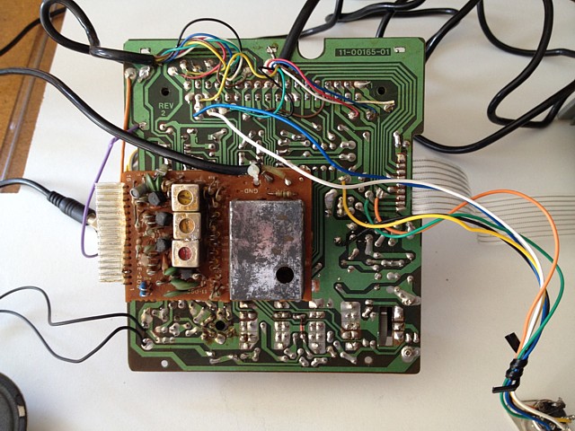
This unit was working initially but the picture quality on the RF output from the modulator was barely viewable. I probed around with an oscilloscope and eventially decided to come up with an AV output mod to improve picture quality. I replaced a couple of resistors whose PCB tracks had lifted, seen in the lower left of the modulator board.
While looking around (I still haven't been able to find a circuit diagram) I managed to blow one of the 4069 ICs on the main board, losing the player 2 graphics completely so I have socketed and replaced both ICs while the PCB was out. I also replaced all the electrolytic capacitors I could find for good measure, unfortunately with no immediate improvement to the picture quality.
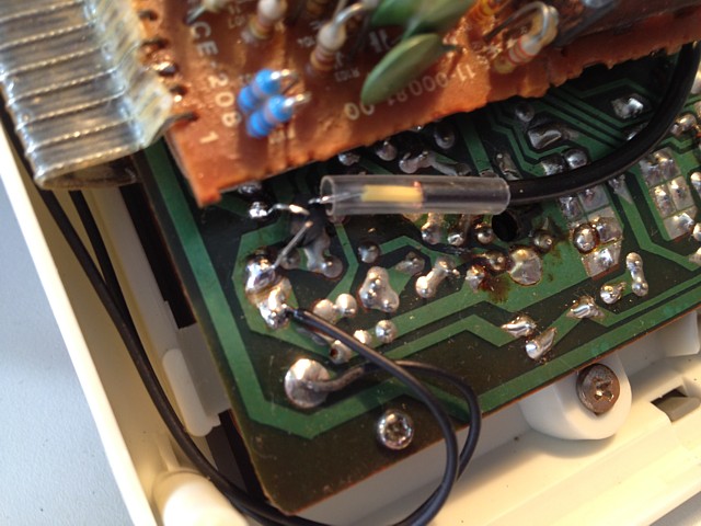
I found a point where all the picture elements and sync are combined to produce Composite Video (with sound carrier, unfortunately) and the levels are about right. For the sake of originality I don't want to disable the RF output with sound so I will just install a buffer to drive the AV output without affecting the existing circuit. The signal goes to the base of a BC557 (PNP transistor) and the common collector goes to ground. The 'emitter follower' output is connected via coax...
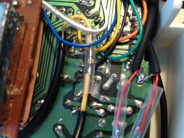
And it comes out here. There is a 330 Ohm pullup resistor from the 'positive' rail (which measures about 6.5 Volts), the resistance is just low enough to drive the output to +1V with an assumed 75 Ohm load. A diode (1n4148 etc.) drops the voltage from the emitter (which is about 0.6V higher than the input signal at the base) back to the correct level for the output. There is no need for ac coupling. The shields of the coax cables are all soldered to ground points, visible in this photo.
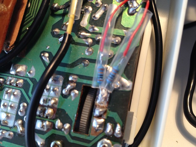
The audio comes from the 'top' of the volume pot allowing the internal speaker to be turned down and sound still be present on the two audio output sockets, each fed by a 100k Ohm resistor to prevent overloading of the circuit and make sure the output is not too loud. The output is basically square waves so you don't want it too loud, believe me...
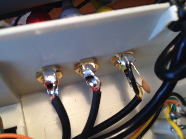
They're all brought to RCA sockets installed into a space on the rear panel. The sound carrier is only required for the RF output and results in patterns on the video when viewed on a high resolution monitor or TV. Older TVs don't really respond to frequencies above the 4.43MHz chroma subcarrier (the sound carrier is 5.5 MHZ) but higher resolution TVs do. To minimize the effect I've just put a ceramic cap, selected by trialling multiple values to reduce the patterns without suppressing the colour.
For best results the sound carrier could be switched off completely if the RF output is not being used. I don't want to permanently disable it but might add a switch later, especially if I can locate a circuit diagram.
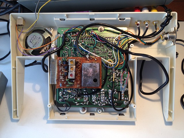
The finished AV mod can be seen in this overall view. The DIN connector visible to the side is for the light gun, used only with the shooting gallery game.
PC-50x Games
PC-501 SuperSportic
PC-502 Motorcycle
PC-504 Car Race
PC-505 Submarine
PC-506 SuperbWipeout
Web Resources (External Links) -
Pong-Story : PC-50x cartridges
Random Encounters # 11 - Car Race GP (Soundic Programmable) - YouTube
All images and text on this website are Copyright.
Contact: jbtech at telstra dot com