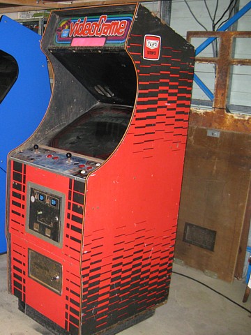
Taito Upright Arcade
Manufactured in Japan around 1984, this Taito Cabinet was intended as a generic unit which could accommodate various game boards. Pre-JAMMA standard, the cabinet wiring is unique to Taito and an adaptor harness is required to install most games.
This machine has been fitted with a genuine Taito Space Invaders Colour three board set, presumably originating from a cocktail machine.
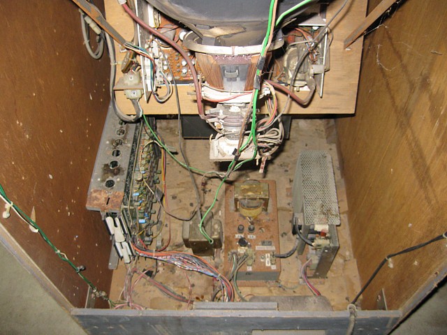
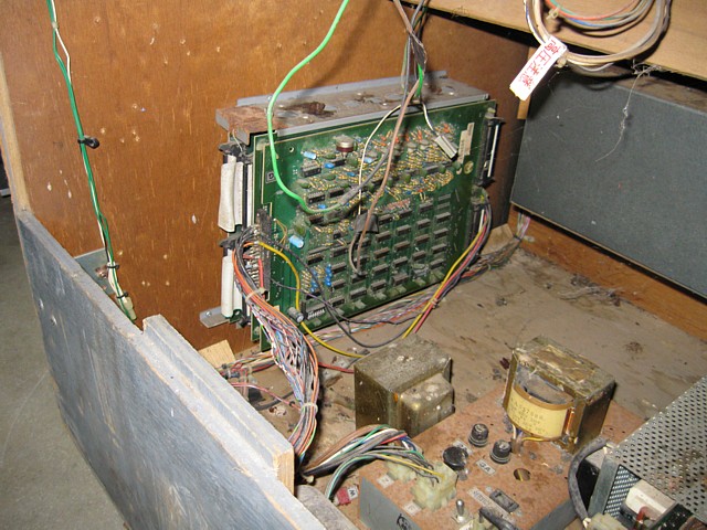
Unfortunately, it has spent too much time 'Beside the Seaside' and there is a lot of surface rust inside! These are 'before' shots so everything looks its worst...
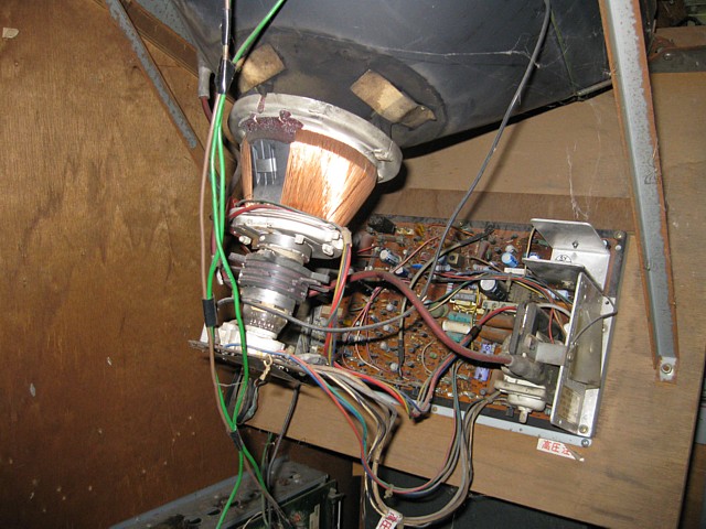
Of course, nothing works though the power rails are there at least. The Toei monitor has a faint raster which is better than nothing so we'll replace caps first then see where we stand.
The Cabinet to Game Board wiring harness 'looks like a Pakapoo ticket' so I'll make a new one. Meanwhile I'll also make a Taito Cabinet to Jamma adaptor so I can use a multi game board to test the monitor and controls, at least until the original board is working. Ideally it would be nice to have both available and just plug either in as required.
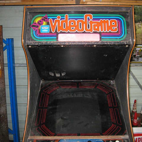
The Marquee light didn't work initially, just needed the 15W fluorescent tube replaced. There's a space in the generic Marquee graphic to put the name of the installed game. No clues as to what it was originally, the paper label which is normally stapled inside the cabinet is also long gone. The CRT can be mounted with either Vertical or Horizontal orientation, vertical in this case to suit the Space Invaders game board.
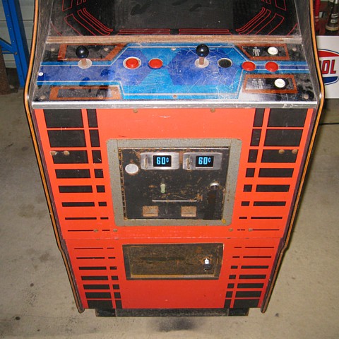
The 'standard' control panel artwork is best suited to a single player layout but I have seen pictures of another one just like this so it is presumably a 'factory' 2 player setup (the other one had a 1942 game board installed). Actually, this one must have been 'upgraded' from a single player, 2 button setup with game instructions on the left side... The condition is not as bad as it looks here, it needs a good clean and a couple of seized microswitches replaced with new ones.
The coin mechs accept 20c coins, obviously the machine was used in a later era and the price set to 3 coins or 60c per credit. I'd like to change the denominations back to the more original green '20c' graphics. 2 new bulbs have them lighting up again.
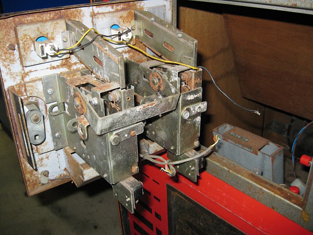
The inside of the coin door looks terrible and wasn't connected but amazingly just needs cleaning and lubrication to make it work. Later on it will need treatment to remove and stabilise the surface rust as well.
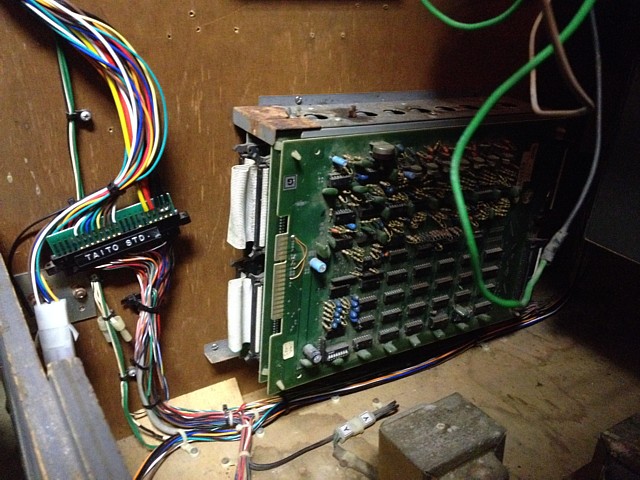
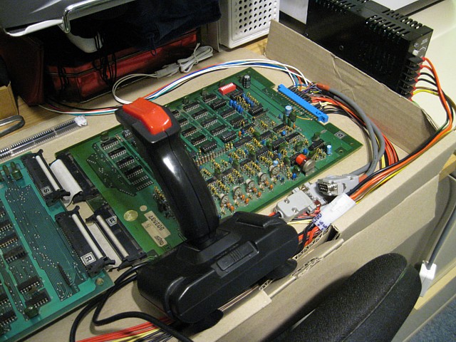
There aren't enough pins in the Molex style Control Panel connector for the player 2 buttons so there is a separate harness for those, like a 'kick harness' seen on other machines. At the game board end the additional wires connect via another Molex style plug and socket, seen here connected to the newly made JAMMA adaptor which leads up to a multi-game PCB.
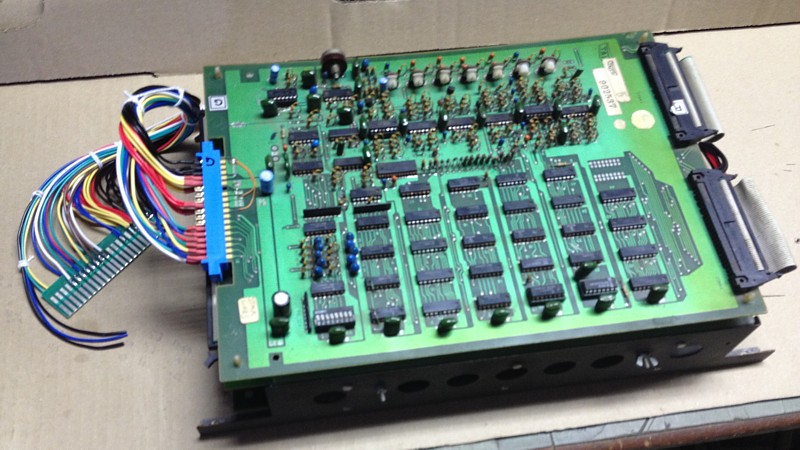
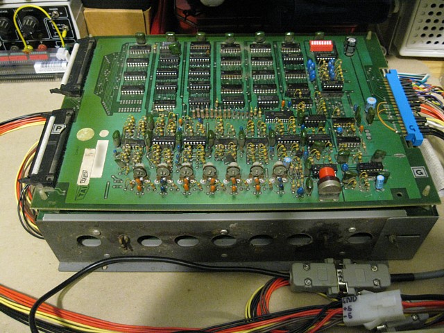
Here's the Taito board set with its new wiring harness. The extra wires not yet terminated are for the Player 2 buttons. The game supports 2 player controls for the cocktail version, obviously the flip-screen feature must be disabled for this upright cabinet.
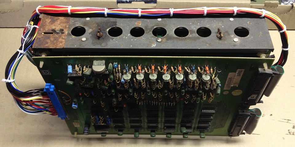
Another shot showing the new harness. I didn't want to cable-tie it all together so I spent the time lacing it with string the old fashioned way. Looks better, I'd say. The bracket which retains the boards in their slots is extra rusty as seen in this photo so I've placed it in some Molasses mixed with water, in a jar for a few weeks. It's an old trick often used with car parts, to dissolve the rust without sanding or grinding.
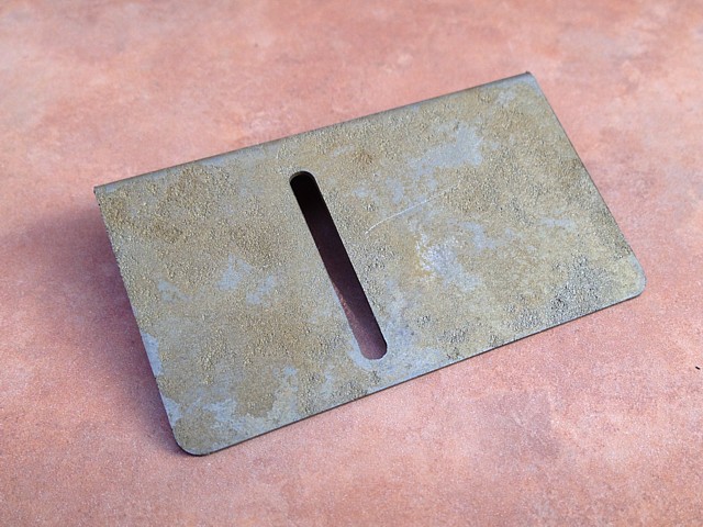
After nearly a month, the rust is completely gone. The bare steel quickly discolours though so will need protection. Originally it had a zinc coating but where it was rusted the zinc is long gone.
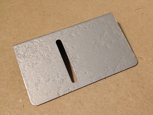
A quick coat of Stop-Rust spray paint and it looks fine. In this close up the pitting is visible but it's not obvious at normal viewing distance and it's an internal part anyway, not normally seen.
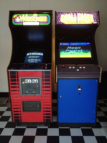
Taito and Gottlieb Cabinets lit up. Multi-game board showing on left screen, MAME on the right. Progress but still a long way to go...
Space Invaders Colour PCB repair
I've been wanting to look into the non-working Space Invaders Colour board set since I bought the Taito upright machine but needed the time and space to set it up properly. Once removed from its metal frame the 3 board sandwich unfolds to become 3-in-a-row, still interconnected by the ribbon cable busses.
Replacing the 51cm RGB Modded Sanyo TV with the 34cm RGB Modded NEC TV, mounted on a monitor arm has provided the extra space on the test bench needed to work on the Taito board set.
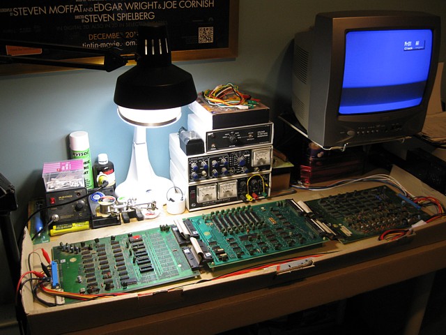
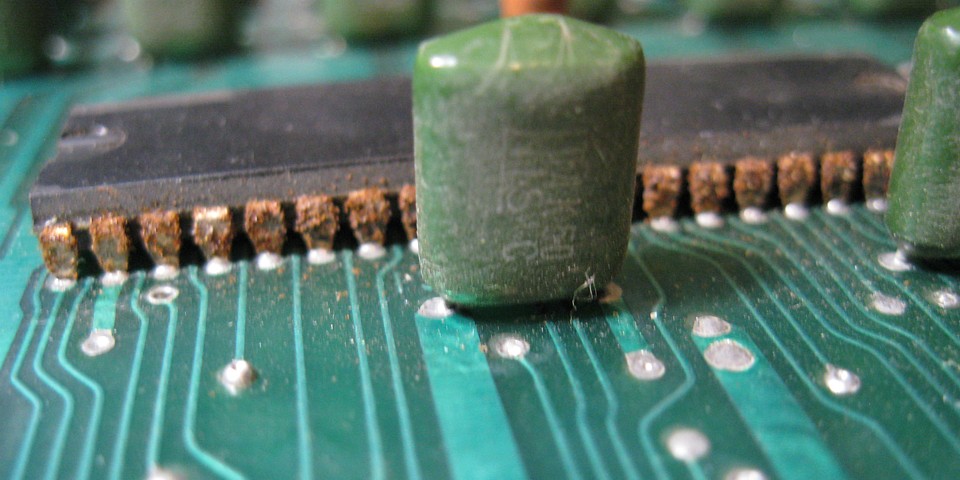
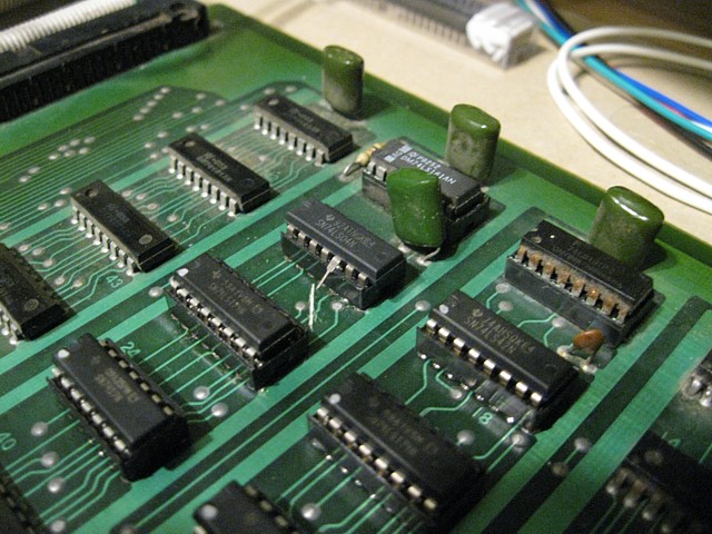
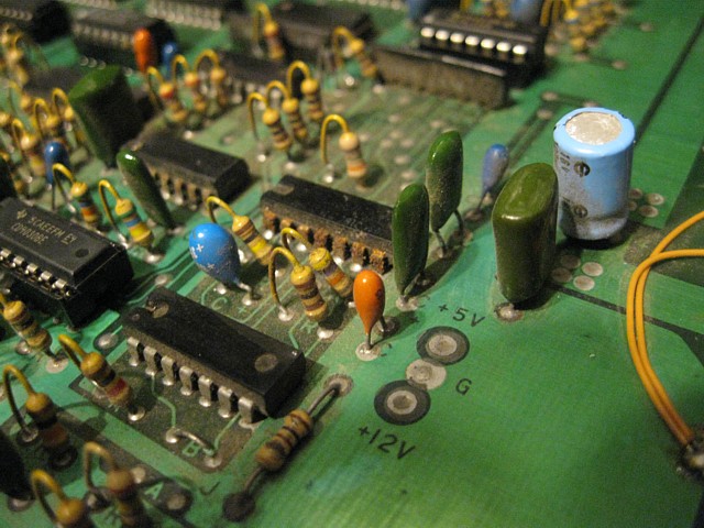
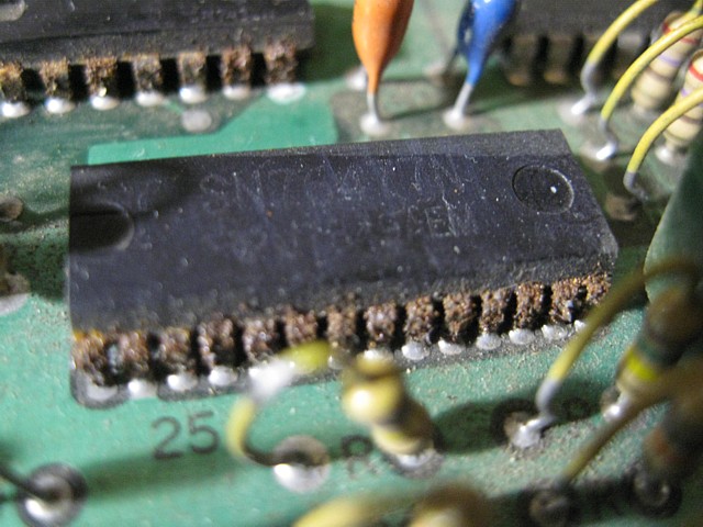
The bench-test lead needs to provide power to both ends of the circuit but the game inputs and outputs all appear on the G connector. When tested in the machine there was no sign of life whatsoever. Looking closely at the PCBs there is heavy corrosion on some of the IC legs so I'm prepared for multiple issues.
To start with I'd like to work out which ROMset it has but the (all 2k) EPROMS which were fitted were various types and those which were labelled were pretty illegible. Two had no labels at all so I just labelled them 'U32' and 'U33'.
I'm afraid trying to remove the EPROMs intact from their sockets was hopeless, their legs were so corroded many just broke off or remained lodged in the socket. In order to try and read them I cleaned the stubs and soldered wire in place of the missing legs but still had trouble recovering much data.
The only EPROM which remained intact was the 'boot' ROM at U36 but when I attempted to read that one the result was all zeros. That could just be due to a poor connection between the EPROM Programmer's ZIF socket and the corroded legs. I did manage to read 'U33' and compared its CRC with known versions from the MAME driver for Space Invaders without any match.
Using the program 'YY-CHR' to view the contents of the EPROM graphically, with a bit of flipping and rotating we can clearly see the familiar characters and the visual similarity to the 'known' Space Invaders CV ROM file (left). The 'U33' file (right) has unusual UFO and Laser Base shapes which I'm not familiar with.
 |
 |
In addition, there is a fifth EPROM, 'U32' which is not present in the CV ROMset at all. Although I had trouble reading it, each attempt yielding different results - there are traces of more, varied alien characters within. Perhaps this set of EPROMs was some sort of bootleg, in this instance fitted to genuine Taito hardware for some reason.

It's Life, Jim but not as we know it...
So, I'll need to replace all the old ROM sockets and install the correct ROMset. In the meantime I've placed a copy of the TestROM in the boot position U36. As far as I can tell, it should work on its own but I have some major issues to sort out first. To begin with, there is no sync to the monitor.
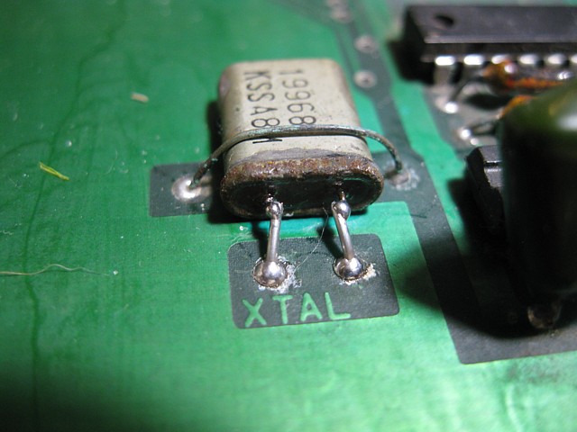
Starting at the Crystal Oscillator IC1, it's reassuring to find the 19.968MHz signal is present though even that turns out to be intermittent. The crystal is mounted flat and its legs have cracked at the bend, leaving just enough of a stub to solder new wires onto which gets that working for the moment.. Following the circuit as the clock frequency is divided down via IC2, IC14, IC5 and IC8 everything seems correct but following that an inverter at IC13 does not appear to be working so I will replace that and continue from there.
The first issue which must be fixed on the Taito Space Invaders Colour board set is the missing Sync signal. Without it there is no display on the monitor to assist with further troubleshooting. Once up and running, the Sync signal also controls the timing of the game program via CPU Interrupts.
The Composite sync should emerge from IC11 on the ROM PCB, a combination of timing signals all derived from the master clock frequency. Initially there was a signal on the IC's output but it was just a steady stream of pulses at about 500Hz. Replacing IC13 corrects the counting logic and the output now looks right, with regular Hsync pulses punctuated by Vertical interval at about 60Hz.
At this stage, there is still no sync detected by the monitor. Tracing the signal as it leaves the ROM board via the the CPU board, it arrives on the I/O board intact. Here the sync signal goes to IC38, a 7404 inverter but its output is dead.
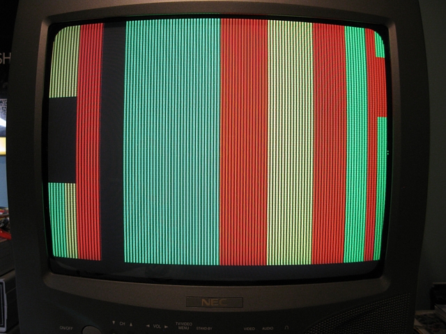
I don't have a 7404 to hand but a 74LS04 should work fine and installing a socket will allow it to be easily changed if required. Upon power up, we now have sync and the monitor springs to life - well, sort of...
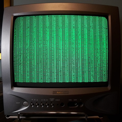
Although the garbage on screen seems disappointing any picture tells a great deal. The colour 'overlay' logic obviously isn't working as we're stuck on green but that can wait. There is some sort of pattern at least which may just be the contents of the RAM on power up. We are making progress...
Meanwhile, researching 'Space Invaders bootleg'(s) and browsing the images for the distinctive Laser Base and UFO graphics, I've found a probable match for the ROMset which was fitted to this system. 'Space War Part 3' also features alternate Invader graphics like those seen in my U32 EPROM and some quirky variations of gameplay.
It's playable in MAME and features quicker laser firing. After the second stage there is a timed level featuring some of the alternate invaders then the characters change again and then back to the 'originals' over progressive levels. It also allows the player to enter their name or initials which appear above their score (or High Score).
The 'bootleg's variations on the game are interesting but given these game PCBs and upright cabinet are all genuine Taito products I think the proper action is to install the correct, original ROMset.
Getting back to the hardware issues, it's difficult to know where to start. At the centre of everything, both physically and figuratively is the 8080A 'CPU' which of course stands for 'Central Processing Unit'. By checking for correct voltages and any activity on its inputs and outputs we may be able to glean some useful clues...
Power supply rails, + and - 5V as well as +12V are all present. The two phases of clock input (12V signals at approx. 2MHz) are also present. Now checking the control and status lines 'we have a problem...'
The Reset line (active High) is stuck on. Tracing that back to the I/O PCB, there is a watchdog timer consisting of 2 cascaded 74LS161 counters at IC17 and 21 with an override from the 'Power On Reset' input on the G connector, via a 74LS04 inverter at IC22. This inverter also has a dead output, causing the reset signal to be continuously set.
Replacing the inverter, the watchdog timer is now counting and outputs a reset pulse about every 4 seconds which appears to be correct behaviour given that the software is still not running or resetting the count - there must be other problems to solve. Returning to the CPU control inputs, the 'Ready' input is not active which would leave the CPU in a 'wait' state.
The 'Ready' signal comes from a 74LS74 Flip Flop at IC38 which seems to be working but its 'D' input is always low. This in turn comes from a 74LS174 at IC37 which does have signals on its inputs and appears to have a dead output. So I'll replace IC37, hopefully correct the 'Ready' signal and see if there is any new CPU activity.
The very aptly named 'Space Invaders' board set has taken over my test bench and looks like being there for a while yet. I've already replaced three faulty ICs, each making incremental improvements but as yet the boards are nowhere near working. Aside from the ICs which are faulty there are many which are so corroded they will need replacement at some point even if they are working at the moment.
I never thought that 'High Tech' Digital Electronics circuits would suffer such 'Low Tech' issues as rust but that's exactly what's evident here. Testing some of the broken IC legs with a magnet confirms they have a high Iron content, they're possibly just Tin Plated Steel. The legs of other ICs which seem unaffected are probably tinned copper - a much more suitable material for the purpose - or maybe they just have better quality plating.
After replacing the 74LS174 at IC37 I looked again for the 'Ready' signal arriving at the CPU but found it was still low. So it appears the signals at the inputs of IC37 must be incorrect, resulting in no output. In the absence of a 'Ready' signal the CPU should enter a 'wait' state so checking the 'Wait' signal output on pin 24 of the CPU should confirm this.
Upon investigation however there is no activity on the 'Wait' pin or any of the CPU's control output pins. They are all stuck somewhere between Low or High (TTL) logic levels so it looks as if the CPU is faulty. It needed to be replaced anyway as it is severely affected by corrosion as the above image shows.
So I've ordered a couple of 'new' 8080A CPUs (they haven't arrived yet but from the product image they appear to have been manufactured in 1979 so fingers crossed). In the meantime I've amused myself by making up a new label to attach to the cabinet, maybe on the back...

My 'Brand New' 8080A CPUs from 1979 have arrived (I bought a spare, just in case). I'd already removed the old one, cutting the rusty pins to desolder them one by one and installed a new 40 pin socket so it's ready to plug and play - well, hopefully.
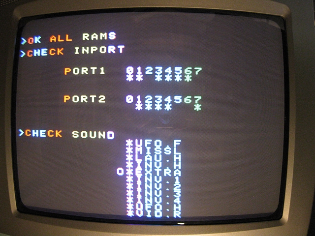
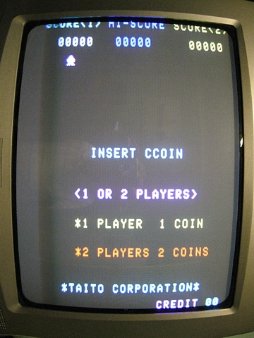
So, plugging it in and powering it on I get this:-
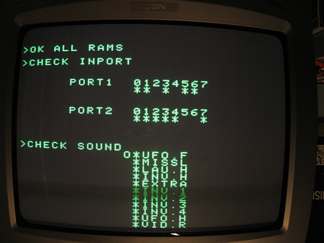
Actually, it displays upside down so I've inverted the photo to read it more easily. This is terrific progress even though multiple issues still need to be sorted. Most annoyingly, the watchdog timer is not being cleared so the whole thing continues to reset every 4 or 5 seconds.
Tracing back, it turns out the watchdog should be cleared by a signal called PORT6 which comes from IC18 on the I/O PCB, a 74LS42. Fortunately, given the state of this PCB I'd already ordered several of the more common components to have these on hand if required. Replacing IC18 sorts out the watchdog timer issue.
Turning my attention to the colour overlay circuit which is not working and stuck on green, now even the green is beginning to fade in and out so it needs to be sorted before we lose the display altogether! (If all else failed, the Black and White image prior to the colour overlay should still be present, on the 'T" connector).
In the colour overlay circuit, the video signal is gated to the red, green and blue outputs using a 7432 Quad OR-Gate at IC37 which appears faulty. I don't have the exact part but do have a 74S32 which will work. The only issue here is the higher input current of the 74S family as three gates are driven in parallel by IC38 which I had already replaced, using a 74LS04. I now have the original type 7404 on hand which can supply a higher output current than the 74LS family so I also swap this part which is already socketed.
Having done that and expecting more colour I'm surprised to find the image is now stuck on red. It turns out this is caused by the BOMB signal which should only flash the display red when a laser base is hit.
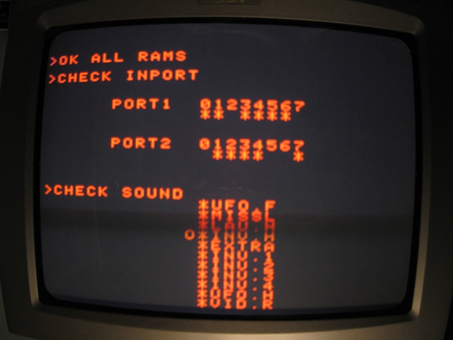
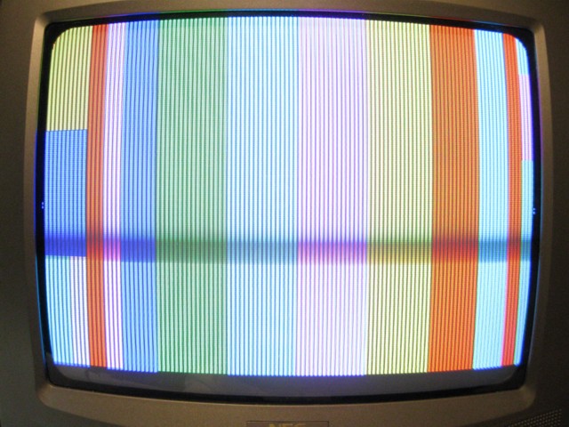
The BOMB signal comes from IC23, a 74174 which appears faulty. I have a 74LS174 which should work fine in this case and install that. Now we have colour but there is a blank strip and a distinct lack of blue in the image. This photo was taken during startup, prior to text generation so the entire overlay can be seen and hasn't been 'flipped'.
Looking at the Blue signal, one stage before IC37 is IC39, a 7400 which has no output. Replacing that with a 74LS00 should be fine as it only drives a single input of IC37. Now the colours seem correct, at last.
Having (finally) the image looking right I move on to multiple issues with the sound. I had a speaker connected to the test lead at first but unplugged it till now as the rather annoying 'UFO Hit' sound has been playing almost constantly along with some other snaps, crackles and pops.
The sounds are selected by signals SX0 through SX10, which come from 2 x 74174 at IC23 and IC19. I've already replaced IC23, to correct the BOMB signal which is linked to the Laser Base Hit sound. Now I find that IC19 which controls other sounds such as the UFO Hit, is also faulty with outputs stuck somewhere between logic High and Low.
Replacing IC19 also with a 74LS174, all the signals now appear correct as the Test ROM selects each in turn. This is only the first stage however, followed by 2 x 7417 Hex Open Collector buffers and these also appear to have faulty outputs.
Aside from the obvious corrosion problems, the number of ICs especially on the 'top' I/O PCB which have failed seems extreme, consistent with a nearby lightning strike or severe brownout. I've already checked the cabinet wiring and power supply and found no major issues, in fact I have been running a multigame board in the cabinet while this PCB set is out of action.
I don't have any 7417 ICs to hand so I'm ordering some and will wait till they arrive before looking further into the sound issues. I prefer to troubleshoot problems such as these in a systematic manner, stage by stage.
But there are plenty of other problems to be going on with so I'll sort out the input ports next.
The input ports read the DIP switches as well as the Player 1 and 2 controls, coin input, start buttons and Tilt. Again, there seem to be multiple issues. IC2 and IC3 are 74LS14 Hex Schmitt trigger inverters connected to the switch inputs, some of their outputs don't match TTL levels. In this case I think corrosion on the IC legs is the issue so I can't resolder them with any confidence, they must be replaced. Likewise, the 74LS153 input selector at IC6 appears to intermittently have incorrect outputs, as it is also quite corroded the only option is to replace it.
The DIP switch itself is also quite intermittent, obviously the internal contacts have become tarnished or corroded but I don't have a spare so I'll order one. Apart from that, having replaced the three IC's the inputs now appear correctly on the test screen.
So now seems a good time to remove and replace those corroded ROM sockets and install a new set of four 2716 EPROMS programmed with the correct 'sicv' ROMset. It's time consuming but important to check every PCB pad and track before installing the new sockets and soldering them in place. I've reinstalled the fifth socket just in case I decide to run a different ROMset at some point.
 |
 |
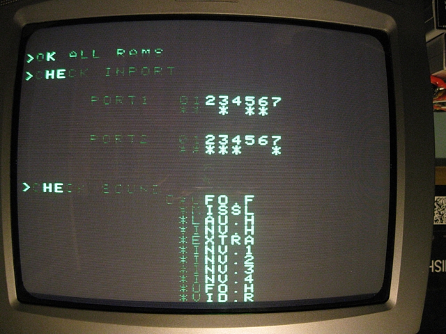
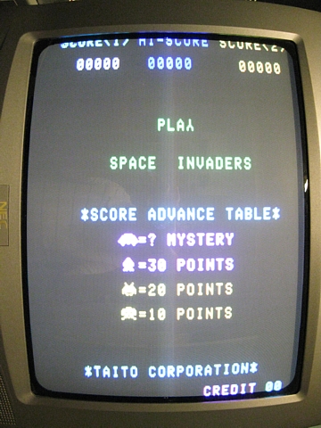
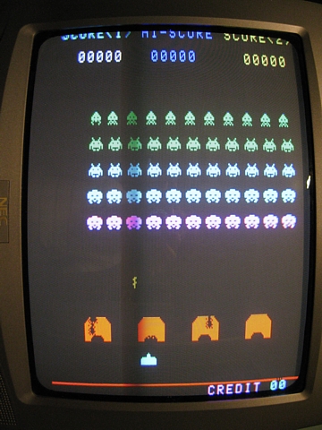
I'm thrilled to see it running properly at last - I've rotated these photos to show the image right way up. I've checked the control inputs are all working, I can replace the DIP switch and get back to the sound problems when my latest parts order arrives.
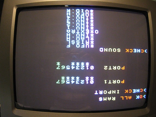
My Space Invaders Colour three board set is working now apart from the sounds. There are a number of problems in that section so I've put the TestROM back in position U36 to assist with troubleshooting. The TestROM repeatedly triggers each sound in turn which is easier than trying to keep the game playing while making measurements at the same time.
If the game boards were installed in the machine, with its vertically oriented CRT the TestROM text would display sideways however on my testbench TV monitor it displays upside down.
Although originally intended for a cocktail configuration, in this instance to suit the upright Taito cabinet the screen flipping function has been previously disabled by cutting the track which carries the VIDEO INV signal to IC22 pin 5, and linking that pin to ground. A downside of disabling VIDEO INV is that the Player 2 colour overlay is never used, the Player 1 overlay is always active.
To test that the Player 2 overlay and screen flipping do work and to display the TestROM text right way up, I've temporarily installed a spare 74LS04 with pin 5 bent away from the socket and allowed to float High, into position IC22. This leaves the video output and colour overlay set in Player 2 mode.
Now the Test screen displays correctly we can move on. I've also replaced the two previously mentioned faulty 7417s at IC20 and IC24 so it's time to see which sounds are working and which are not, as per the video below.
So, there are a few completely missing and the (MISSL) laser base firing sounds wrong, we're just getting 'peep' where it should be 'pssssssht' or something like that. There's a noise generator which should create the white-noise like 'sssssh' part as well as the laser base hit rumble, both of these are missing.
One of the most fondly remembered aspects of Space Invaders is its distinctive, inherently 'retro' sound effects. They're individually generated using 1970s analog synthesiser technology. Want a sound effect? Start with an oscillator, maybe change the wave shape to add a few harmonics. Modulate that with another, lower frequency oscillator or ramp generator to add a bit of warble, mix in some noise, top it off with a little decay and hey presto - its the space age!
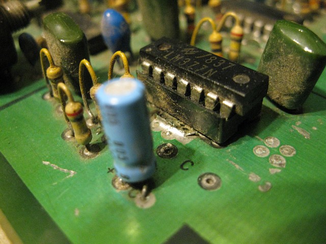
The simplest and most iconic sound of all is the menacing 4 note 'March of the Invaders' which is created by a garden-variety 555 timer IC (in this case 1/2 of a 556 dual timer IC, the other half gives us the bonus laser base sound.) It's still working after 40 years of use, abuse, neglect and an impressive amount of rust on the IC's legs!
I have to wonder if that Space Invaders sound was inspired by the even more menacing Bruce's theme from the 1975 movie 'Jaws'. Either way, I think I'll leave this original IC in place whilever it continues to work, out of respect for its resilience.
A bit of trivia about 'Jaws', there is a brief scene in the movie where a row of arcade machines are being played right at the beach side. In the foreground a 'Killer Shark' Electro Mechanical shooter by Sega is featured, just behind it is the unique profile of a yellow 'Computer Space' by Syzygy / Nutting Associates.
Given my experience with this Space Invaders PCB set I can fairly safely say that if machines like that were actually used so close to the beach for any length of time their parts would have just about rusted away completely!
Back to the issue at hand - following the individual sound generators there is an LM3900 mixing amplifier at IC4 with an inverting stage to drive the LM377 complimentary 'bridged' output amplifier at IC1. One of the control signals, SX5 is used to enable or mute all the sounds at the mixing stage IC4.
Here there is another problem - when enabled the overall sound volume is very low and when the sound is supposed to be muted there is a fairly loud crackling noise. So, looking at the signals with an oscilloscope IC4 itself appears to be the culprit, most noticeably the output from pin 4 and its complimentary, inverted output from pin 10 do not look symmetrical.
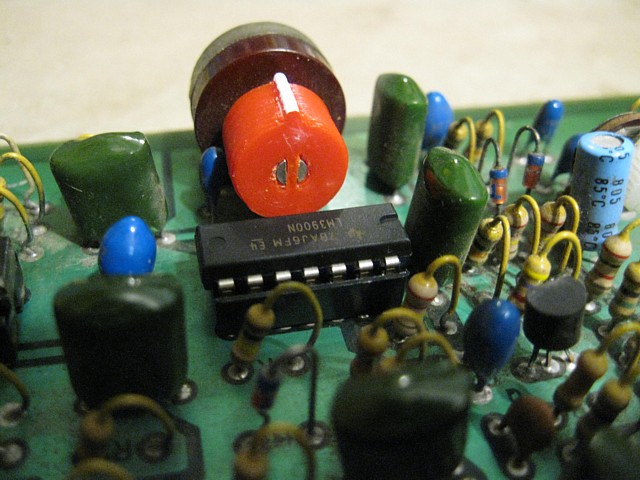
So, to replace IC4 I'd like to install a socket as well but the screwdriver-slotted metal shaft of the main volume Pot is quite close and might be difficult to adjust if the IC sits much higher. The solution (well, my solution anyway) is to 3D print a small knob for the Pot which pushes onto the shaft, engaging the slot - prior to installing the new socket and IC4.
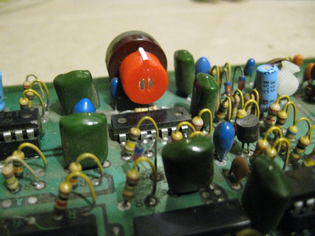
The new knob before and after replacing IC4. I printed it with red filament and marked the ridge with white paint to match the new red and white DIP switch. That tantalum capacitor touching the knob just needed to be bent away slightly to allow full range of movement!
Replacing IC4 seems to have corrected both the low volume and crackling problems. Before moving on to the individual sounds however I did notice an empty spot where a capacitor should be. It's part of the final amplifier stage around IC1 and may have just broken off when the IC was replaced (and socketed) at some point. It wouldn't be terribly noticeable audibly, it should just provide a bit of high frequency rolloff / noise suppression on one side of the bridged audio output. The other half has a similar circuit which was still intact.
After installing a new 0.1uF greencap we're ready to look into those missing sounds. The majority of these problems are most likely caused by faulty ICs although there is some possibility of discrete and passive components having failed or bad solder joints, broken PCB traces etc.
I've ordered spares of all the ICs in this section but some are obsolete and not readily available. In the case of the SN76477 (UFO flying sound) and 4006 (CMOS, part of the 'noise' generator) I have ordered some, presumably old stock which have not arrived as yet so I will leave these sections for later.
The most commonly used part in this area is the LM3900 quad op-amp which I now have in stock so this should sort out at least some of the problems. In addition to the mixing amp at IC4 there is a row of 6 LM3900s from IC30 to IC35, which generate many of the sounds.
Beginning with IC 30 and 31 which are responsible for the 'Target Hit' (Invader hit) sound, IC30 is already socketed and the socket contacts don't look corroded (a bit dull maybe) so replacing the IC in the existing socket, the Invader Hit sound comes to life! - therefore U31 (or at least 3/4 of U31) appears to be OK. If this sound becomes intermittent at some point I might replace the socket, meanwhile if it's not broken...
Next sound off the rank is the 'UFO Hit', which is working. It's generated by IC32 and 1/2 of IC33 so for the moment at least we'll assume both of those ICs are OK and don't need replacement.
The 'Laser Base Hit' sound uses part of IC33 and part of IC34 as well as a signal from the 'noise' generator at IC28 and IC29. Working on the assumption that IC33 is OK, I replace IC34 which is also already socketed. The result is that the 'Laser Base Hit' still isn't working, just a slight 'thump' being heard but I do notice the 'Laser Base Firing' sound which uses IC34 and IC35 now has a bit of sustain (and a slight pitch shift?) added to the 'peep' sound. As both of these sounds rely on a signal from the 'noise' generator I think once that is working both sounds should be complete.
Looking at the circuit diagram for the noise generator, part of IC29, a 4030 is configured as a free running oscillator whose output from pin 11 feeds into pin 3 of IC28, the 4006. Testing for this signal and finding no activity I'm certain the 4030 has failed. Replacing that and looking again there is now a signal there but still no 'noise' output from IC28 so I will try also replacing the 4006, when spares arrive.
The only remaining issues to solve on the Space Invaders Colour PCB set are 3 of its sounds - the Laser Base Firing sound which is missing the 'white noise' component, the Laser Base Hit and UFO Flying sounds which are both missing entirely.
I've already replaced IC29, part of the 'noise' generator, a 4030 CMOS IC which got the initial oscillator part running but there's still no output from the 4006 shift register, IC28 so it's time to try replacing that also.
The 4006 is obsolete and becoming scarce but I've sourced a few from overseas which have just arrived. Removing the original part and replacing it, along with a new socket gets the 'noise' generator section working. So testing the sounds again, now the 'Laser Base Firing' sounds just as it should.
Somewhat unexpectedly though, the 'Laser Base Hit' sound is still missing. A quick trace of the circuit reveals the 'noise' signal is disappearing at IC33. Initially I'd assumed IC33 was OK as 1/2 of the IC is known to work, producing the 'UFO Hit' sound. It seems the other 1/2 of the IC is not working so replacing IC33, also installing a new socket gets the 'Laser Base Hit' sound working too.
And finally, the 'UFO Flying' sound which is generated by the SN76477 dedicated sound generator IC25 - well the following picture speaks for itself. This IC has an uncommon package size, a 28 pin SDIP with a smaller pitch of 0.07" compared to 0.1" and a row spacing of 0.4" compared to 0.6" for a standard DIP 28 pin package. Now well and truly obsolete, the only available spares would be old stock or 'pullouts' which I suspect is the origin of the one which I purchased and have just received.
Nonetheless after removing this one, cleaning away the powdery rust particles and soldering in the 'new' old replacement the 'UFO flying' sound is brought back to life. Take care when ordering spares as this IC was available in both standard DIP and smaller SDIP package, as used here. In a photo without any reference scale it is very difficult to distinguish one from the other.
Having sorted all the sounds the game is now fully working - to test it properly I've wired two DB9 connectors (for Atari 2600 joysticks) to the 'G' connector on the bench test lead with Left, Right and Fire buttons as well as using 'Down' for coin input and 'Up for 1P and 2P start on the respective joysticks. I also have a Quickshot joystick for Atari or C64 with 2 buttons (luxury!) so I've wired button 2 to 'Tilt' just to test that function out as well.
After checking the game plays, all the controls and sounds are operational it's time to put the boards back into their metal frame for a final test. Though everything's functional now and the PCBs themselves look fine there are still some ICs which are showing signs of corrosion - none as bad as the ones which I've already replaced (which were not working) but at some point, a number of these might also fail.
If this was a customer repair, anything which looked like failing in the near future which was viable / economical to replace would be done so for the sake of ongoing reliability. But for my own use, is it worth spending extra time and money now to replace parts which are still servicable or would it be better to address any further issues as they arise?
A difficult question - fortunately I am very well equipped with a state-of-the-art computerised diagnostic system which can be relied upon to solve complex issues such as this. Lets see what it comes up with -
Fair enough, I'll take it up to the Workshop and put it back in the machine. After all, what could possibly go wrong? 'Open the pod bay doors please Hal'...
Since repairing the Space Invaders Colour PCB set and reinstalling it in the Taito upright cabinet I've been giving it a bit of play and it's been pretty reliable so far. At one stage the 'bonus laser base' sound went missing so I did replace that rusty 556 timer IC mentioned above, only to find that wasn't the problem.
The 556 controls the 'pulsing' of the bonus sound but the actual tone comes from the sync circuit via one of the 50 way IDC ribbon interconnect cables and the respective pin which carries the tone signal was intermittent.
I've purchased some new ribbon cable and IDC sockets to make new interconnect cables but since reseating them all at the time they haven't failed as yet. If and when they do I'll replace the full set.
Experience with this repair and my existing bench test setup has been a great help with the Logi Tec Space Invaders Colour TT which I've recently purchased.
Although there doesn't seem to be any documentation available for the Logi Tec version it has a similar architecture and runs an almost identical program to the Taito original, albeit using different hardware and PCB layout.
It turns out the colour overlays used for Player 1 and 2 appear identical for the two machines though the Logitec PCB uses a 7th 2708 EPROM for the overlay information while the Taito PCB set has a pair of 1k x 4 Bipolar PROMs, one for each overlay.
Following up on that, the bipolar PROMs used in the Taito version contain 4 bit data with bit 3 always being clear and apparently unused. Bits 0 - 2 are the same as the LogiTec version with bit 0 being Red, bit 1 is Blue and bit 2 is Green.
So, as an experiment I'm going to do a little ROM hack to try with the 'sicv' ROMset in MAME, a new cv01.1 file to replace the original. I'm calling this one STEALTH INVADERS and it's for anyone who now finds Space Invaders too easy, having had 43 years worth of practise and all...
I've given the invaders 'stealth' technology with a few rows of 'black' overlay. The game plays exactly as original but you can't see the invaders until they get a little closer, you have to shoot at them 'blind'.
If your laser base is hit you will briefly see the position of the invaders in the red glow of the explosion. I've also given the UFO a bit of colour, it's supposed to represent the Doppler effect as the UFO approaches appearing blue on the left and passes shifting to red on the right. (it doesn't make any sense right to left but there you go...)
Stealth_Invaders_cv01.1 Hex file
Note: this is NOT a complete MAME ROMset, just a custom colour overlay which should work with the original 'sicv' ROMset by substituting the cv01.1 file. It should also work on actual hardware but you would need a blank PROM and suitable programmer to install it. It wouldn't work on Black and White versions, obviously but I guess you can achieve much the same result with about 5 strips of black electrical tape!
To try it in MAME, put the unzipped 'sicv' folder in the Roms folder and replace the original cv01.1 file in there with my version (rename it so it matches the original). be sure to remove the sicv.zip file from the Roms folder to prevent the original file being found there then run 'mame64 sicv' (or just mame sicv for 32 bit) from a command prompt to avoid the MAME UI which blocks any ROMsets with files which do not match expected checksums...
Enjoy!
Web Resources (External Links) -
Romhacking.net - Utilities - YY-CHR
SPACE WAR PART 3 SPACE INVADERS CLONE BOOTLEG 1978 MAME ARCADE GAME spacewr3 - YouTube
Stealth Invaders - gameplay demo - YouTube
All images and text on this website are Copyright.
Contact: jbtech at telstra dot com