Sinclair ZX80 / ZX81 replica
Following on from the build of my Ohio Superboard II computer reproduction, here's another project based on a classic home computer from 1980 - the Sinclair ZX 80.
I first saw an original one around that time while I was still at school, someone was looking to sell theirs and presumably upgrade to some other computer. That may have been a common occurrence with the ZX80 which was definitely an entry level into computing and anyone who took to the new science would soon be moving on to something with more ability.
My recollection is being less than impressed by the tiny plastic computer with its infuriating membrane keyboard and inverse display which seemed to suffer from a nervous twitch. I already had my original Ohio Superboard (which by comparison seemed like a super computer!) and passed on the offer at the time. Of course now I realise the ZX80 was destined to become an icon in its own right and wish I had picked up a bargain while they were going cheap.
These days I'd love to own an original Sinclair ZX80 as it was a milestone in the history of personal computing, especially in the UK where it was manufactured and sold for less than 100 pounds. In Australia they were far less common, now quite rare and highly sought after. Their distinct appearance and quirky operation no doubt made a lasting impression on anyone who ever attempted to use one - even if only remembered for its obvious limitations.
Given that an original ZX80 is unlikely to come my way anytime soon I began to look into reproduction projects. A number of reproductions and clones have been produced including some which are open source designs. I would define a reproduction as one which attempts to exactly reproduce the original unit in every detail where possible, while a clone may function like the original and be compatible with original software but may use different hardware extensively.
Somewhere inbetween those two definitions I would place a 'replica' as something which looks and works like the original but may include some concessions to modern components or enhancements to the original design.
My initial search led me to an amazing reproduction project by Grant Searle (see link below) which recreates the computer in extreme detail right down to a photographic rendition of the PCB layout. The Sinclair PCB appeared to have been laid out by hand rather than computer generated, many of the tracks taking a curved path rather than a straight line approach.
Grant has meticulously recreated the artwork for both sides of the circuit board which he then printed onto transparencies and transferred to a blank PCB using a photo resist, development and etching process followed by drilling and tinning of the PCB tracks. His final product resembles the original in every respect.
Impressed as I was by this incredible attention to detail, I don't feel up to the task of etching my own PCB so continued to look for a project which could be based upon a commercially produced PCB instead. I didn't have too far to search and soon found another excellent project, by Wilco2009 on Github (see link also below).
The Wilco design is based upon the original circuit and resembles the Sinclair PCB with the majority of components in the same locations but does away with the RF modulator in favour of some additional ICs which correct the video signal, adding a 'back porch' period following horizontal sync - a concession to more modern displays which have trouble with the non standard video signal produced by the original ZX80.
Other enhancements include a single 32k Byte Static RAM IC to replace the 1k Byte (2 x 2114 IC) originals, also a much larger 64k Byte EPROM with bank selection by a DIP switch to allow a choice of 8 different 8K Byte ROM versions. The latter, in conjunction with an NMI (Non Maskable Interrupt) modification which has also been incorporated into the circuit allow the PCB to function as a fully compatible ZX81 model in addition to the original ZX80 mode.
Although straying slightly from original specification, these are all useful additions which to some extent were available at the time as 'optional' extras. Most users who persisted with the ZX80 would have found a 16k Byte RAM expansion pack essential as the original 1k Byte of RAM was insufficient for almost any meaningful task.
When the ZX81 was released one year later, ZX80 users could also buy an upgrade kit which included a new 8k ROM (to replace the original 4k) and keyboard overlay. Completing a small hardware modification then allowed the original ZX80 to be fully compatible with the newer ZX81 model. The ZX81 combined the function of the ZX80's individual logic ICs into a single custom IC, reducing the component count on its PCB but was functionally the same as the original ZX80 hardware.
So, having settled on a project the first step was to send off the included files to have a small batch of the PCB made and begin assembling a kit of the required components. The Wilco PCB is a modern CAD design with all the detail required for production including track layouts, plated through holes and routing, top and bottom solder mask and silk screen overlays.
As the original Sinclair PCB had no solder mask at all on the component side the choice of colour for this project was just a matter of preference so I went for white, with black silk screening. I had begun gathering components already but once the PCBs arrived the project acquired a physical presence. There were no problems with getting the PCBs made, my sincere thanks to Alejandro, Wilco2009 for the great effort in creating its perfect design.

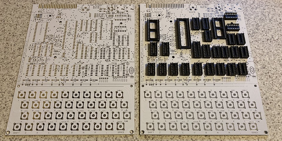
Here are the PCBs and I have already begun by soldering the IC sockets in place. Given the number of passive components on board however it may be easier to begin with resistors, which lay flat against the PCB then IC sockets, followed by capacitors, semiconductors, DIP switch and connectors before adding the ICs themselves. For a digital computer circuit there do seem to be a lot of passive components on the PCB, more on that later.
Assembly of the ZX80 / 81 PCB has been fairly straightforward, I already had several of the required ICs including the CPU and RAM as well as most of the smaller components so just placed orders for the remainder. Along with some of the logic ICs I had no 27C512s to hand so added that component to my parts order. The only version of the 27C512 my supplier had in stock was a OTP (One Time Programmable) IC which is not eraseable so is effectively a PROM.
The 3.5mm sockets require the correct footprint to match tha PCB layout and fortunately were available locally, I found Jaycar Part No. PS0133 was suitable. I've read some criticism of the ZX80 for using the same 3.5mm connector for its DC power supply as for its cassette interface, suggesting this could damage the unit if plugged into the wrong socket but notice in the original owners manual Sinclair advised that plugging the DC power connector into the wrong socket would do no harm.
That aside, I've also noticed the Wilco PCB (build 039) provides some additional contacts to substitute a 'standard' DC barrel style connector for the 3.5mm DC in jack. I may swap this over to suit a plug pack type power supply which I have for the computer, that will save changing the existing DC plug on the power supply to a 3.5mm jack.
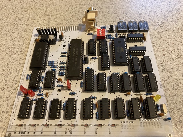
A couple of components which I haven't sourced correct parts for as yet; the RCA video connector was not available locally so I've temporarily subsituted a dual RCA version. Similarly, instead of the 3 way DIP switch I only had a 4 way version handy so rather than cut off 2 pins I've temporarily fitted an 8 way IC socket with 2 socket pins removed and plugged the DIP switch into that. Eventually I will replace both with correct components before fitting the PCB into a 3D printed case.
But I'm getting ahead of myself, before I attempt to 3D print a case for the computer I first need to get the PCB working including its all important membrane keyboard. I've avoided that issue until now, initially I thought a 'standard' replacement membrane for the ZX80, available online would be the best solution but that wouldn't allow for separate key overlays to suit ZX80 or ZX81 mode.
Reading some of the instructions and comments on the Wilco2009 site revealed an important detail; the contact pattern on the Wilco PCB has been designed to suit dome switch contacts. I've seen these little metal domes used as switches in computer joysticks, held in place with a bit of sticky tape and the exact same principle is used here. After buying a quantity of the square metal domes with 10mm diagonal size I've carefully positioned them and laid a strip of clear tape over each row.
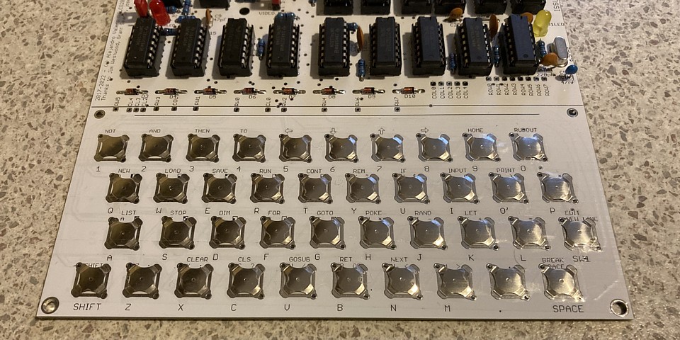
The result surprisingly looks quite neat and the domes actually make good contact when operated with a fairly heavy, clicky feel. I definitely would not recommend this keyboard for word processing applications. The original ZX80 membrane may not have been quite as heavy to operate but if I recall correctly was pretty vague and not much better.
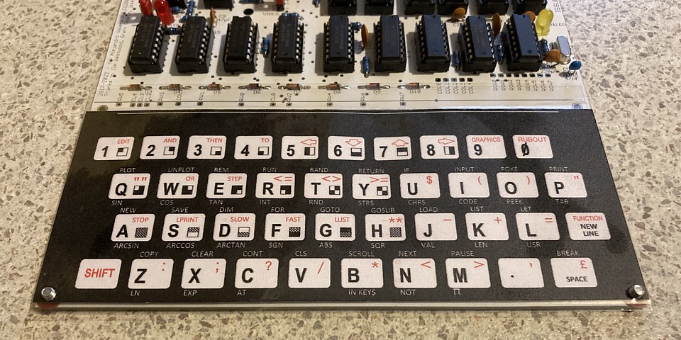
Anyway, the keyboard appears to be functional even without any overlay which resolves the issue of changing the layout for ZX80 or ZX81 mode. Resources on the Wilco2009 site include keyboard artwork for both versions as well as case graphics. I cut, rotated and pasted the ZX80 and 81 overlays together so that when printed on a single sheet of paper then folded over the two appear back to back.
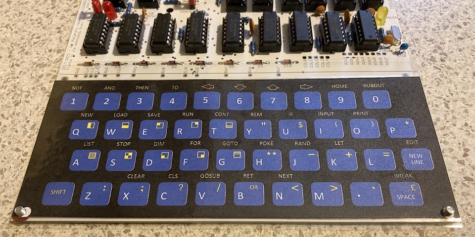
After trimming and laminating the first attempt looks pretty good and will be held in place by the two fixing holes as well as the lid of the case when complete. Blue is the original style ZX80 keyboard overlay or turn around to reveal the white ZX81 layout.
I've completed my assembly of the Wilco ZX80 / 81 PCB and it's time to power on and test. Initially I'm using my bench power supply to provide the 9V DC input, the Voltage is not critical as there is a 7805 Regulator IC on board but the bench supply has a useful meter to indicate the current drawn and an adjustable current limit in case of any circuit shorts. The computer's video output is monochrome composite, which I've connected to the AV input of my workbench NEC CRT TV monitor.
Powering on, there is sync but no video information apparent on the screen. A quick check of Voltages and signals on the PCB using my oscilloscope reveals the +5V is correct, reaching CPU and major components. The 6.5MHz clock signal is present (without that there would have been no sync anyway) and the address and data signals all appear active at the CPU so we may just have an issue in the video section of the computer.
Up until this point I have not spent any time analysing this particular computer circuit or attempting to understand its inner workings. It has so far been an assembly project and taken for granted that the circuit works but when there is some issue which prevents that from occurring is when we really gain an insight into its design - and of the people who designed it.
It's a well known anecdote that the single goal for the ZX80 was to build a computer for the lowest possible cost and any component which was not absolutely necessary would be omitted. Just how far they went to achieve that goal now becomes clear; the Sinclair team must have thrown their design handbooks out of the window upon commencement of this project.
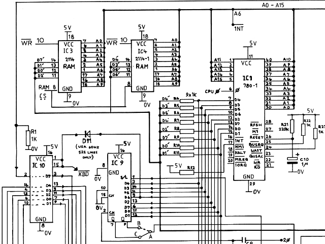
Looking at a section of the original ZX80 circuit above the layout appears fairly conventional with Z80 CPU and 1k Byte of RAM, what's missing is a dedicated video circuit to read out the contents of the video memory. Instead the CPU is tasked with this process, continuously transferring the data to a shift register IC9 which clocks out the graphics information as video. A moveable link selects either normal or inverse video from its Q or /Q outputs.
That is the cause of the Sinclair ZX80's notorious video flicker; while the CPU is processing any user input or program the video display is not maintained. Some software programs and a later hardware modification which became standard in the ZX81 model allowed the computer to prioritise the video output and process other information during the vertical blanking interval of the video signal.
The result was reduced processing speed but a much more useable system which could update video and process information without disruption. Another cost cutting measure evident in the diagram above is a bank of 1K Ohm resistors used to isolate sections of the data buss, normally a bidirectional buffer would be used for this purpose but substituting resistors would save the cost of one additional integrated circuit.
Getting back to the no video issue on my PCB there does not appear to be any output from the shift register as its Shift /Load input pin 1 is stuck high, never loading any data from the CPU. This signal comes from the output pin 8 of a 3 input NAND gate IC 16 seen below, top right of diagram.
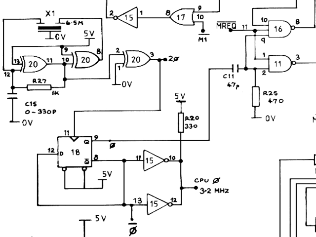
Double checking the output pin 8 of IC 16 it does appear to be always in a high state. IC 16 is a 74LS10 3 input NAND gate so for its output to go low at any time all 3 inputs must be simultaneously high. A quick check of the ICs inputs shows regular activity on pin 11, which comes from the CPU /MREQ control signal. Pin 10 is mostly low, with a regular high going pulse. That leaves pin 9 which is derived from the 3.25 MHz clock circuit.
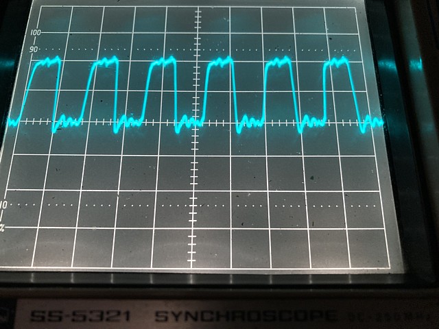
Looking at the clock signal from pin 9 of IC 18 in the image above, at 2V per division on my oscilloscope with the centre line adjusted to 0Volts we see an approximate square wave with a level of about 4V which is a little low but well within valid TTL limits.
This is fed to pin 9 of IC16 via C11, a 47pF capacitor with 470 Ohm load resistor R25 to ground. The signal which arrives at IC9, seen in the image below looks more like a sample from a Jimi Hendrix guitar solo than a digital waveform.
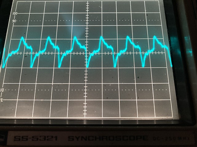
Well, not really as the frequency is much higher but anyway... This was another cost saving measure to create a brief pulse from the rising edge of the clock signal, without using an additional IC. Normally to create a short pulse a monostable IC (also referred to as a one-shot) would be used to create a single pulse on each trigger event, the pulse duration being set by an R-C network but the output would be a valid TTL signal with correct Voltage levels.
Here the passive components have been used directly as a high pass filter to reshape the square wave into something with a short peak which was intended to enable IC16 briefly so the shift register could load data from the CPU and then return to shift mode so that data could be clocked out as video.
The problem here is that signal, being AC coupled with a resistance to ground now ranges between about +2 and -2 Volts so the positive peak is not quite high enough to be reliably detected as a logic high. To be a valid TTL signal high must be 2.4V or above and low 0.8V or less. Anything inbetween these two Voltage levels is invalid and TTL ICs may detect signals within this range as either low or high.
At this point I should mention that there is a slight revision to this part of the Wilco circuit compared to the original, with the addition of a separate high pass filter from the clock signal to IC11 whereas in the original Sinclair circuit the C11 / R25 network connects to the inputs of both IC16 and IC11. A small excerpt of the circuit by Wilco2009 is shown below for comparison to the original above.
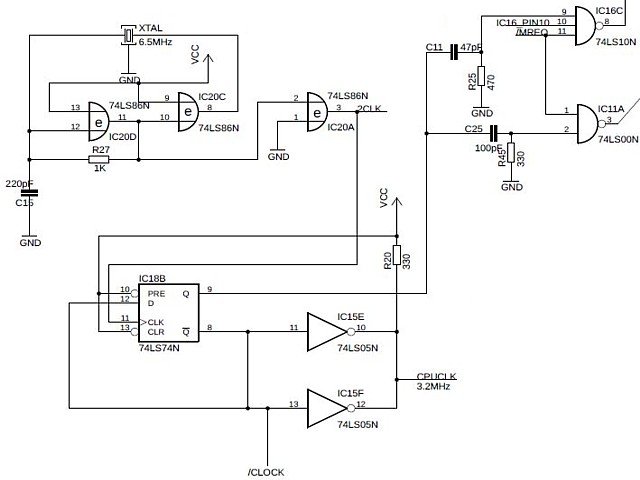
I imagine this revision was to address a similar issue with the integrity of the signals reaching IC16 and IC11 - and may have resolved a problem in some cases but in this instance has not helped. It could be that adding the second capacitor and resistor has increased the load on the output of IC18 and may even be responsible for the slightly reduced level of the clock signal as mentioned above.
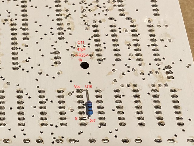
Rather than replacing IC16 (or IC18) it should be possible to resolve the current issue by adding some bias to increase the DC level of the signal at the input pin 9 of IC16. A simple resistor from +5V to pin 9 will increase the DC level but that would also affect the load and time constant of the C11 / R25 high pass filter.
Although the +5V rail is a constant DC Voltage, that acts as an AC 'ground' so a resistor from pin 9 to +5V is effectively in parallel with R25 from an AC point of view. The solution is to increase R25 slightly, in this case I'm changing it from 470 Ohms to 1k Ohm and then placing a resistor of 1k or more from pin 9 to +5V. Beginning with higher values, by trial and error I have settled on a 2.7k Ohm resistor from +5V to pin 9 with a 1k Ohm resistor in position R25.
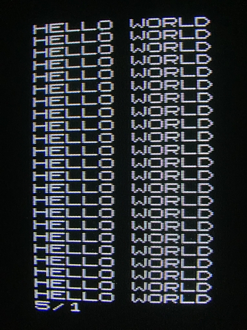
Having done that, we now have video and the characters look sharp. Success!
I've picked up the remaining components to complete my assembly of the Wilco ZX80 /81 PCB. Beginning with the RCA video output connector and 3 way DIP switch, the parts which I had temporarily substituted can now be replaced. The DIP switch selects the ZX80 or ZX81 ROM version to be used and can be fitted to either the top, parts side of the PCB or the bottom (solder side).
This would allow the ROM selection to be made without the need to open the lid of the case if a suitable access hole is made in the bottom panel. I'm fitting the switch to the parts side though as I don't expect to change the selection often. In addition to those two items I'm replacing the 3.5mm DC power input jack with a 2.1mm barrel style DC connector, to suit a 9V plug pack power supply which I already have.
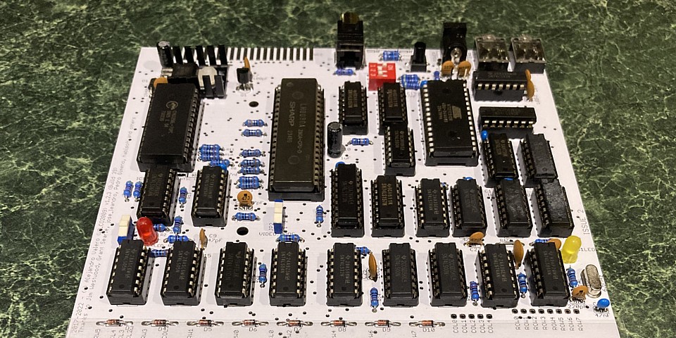
Having done that I realise the polarity of the barrel type connector is centre pin negative whereas I assumed the more common 'centre positive' configuration. Looking at the PCB connections I suspect this was necessary in order to provide a PCB footprint which allows for either barrel or jack style connectors to be fitted.
No matter, I can reverse the polarity of the DC plug on my power supply. The plug is a moulded type so I could either cut that off and replace with a solder type connector or just cut and splice the cable near the plug end. I've seen plenty of messy, unreliable cable joins over the years so will attempt to illustrate a neater, more reliable approach.
Note: This is only for low Voltage, low current connections and never for high Voltage, high power or mains cabling. In the photo below I've cut the cable near the DC plug end and cut one wire about 1cm shorter on both sides, then stripped about 5mm of each wire.
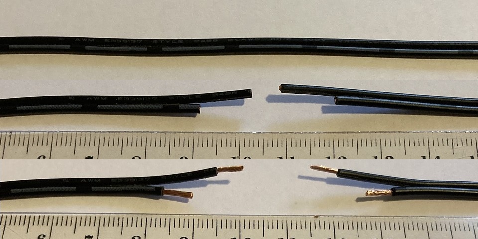
After tinning the bare wires I've turned one cable around to reverse the polarity and cut some heatshrink tubing, two small pieces to cover the soldered joints and one larger piece about 4cm long to cover the entire joined area.
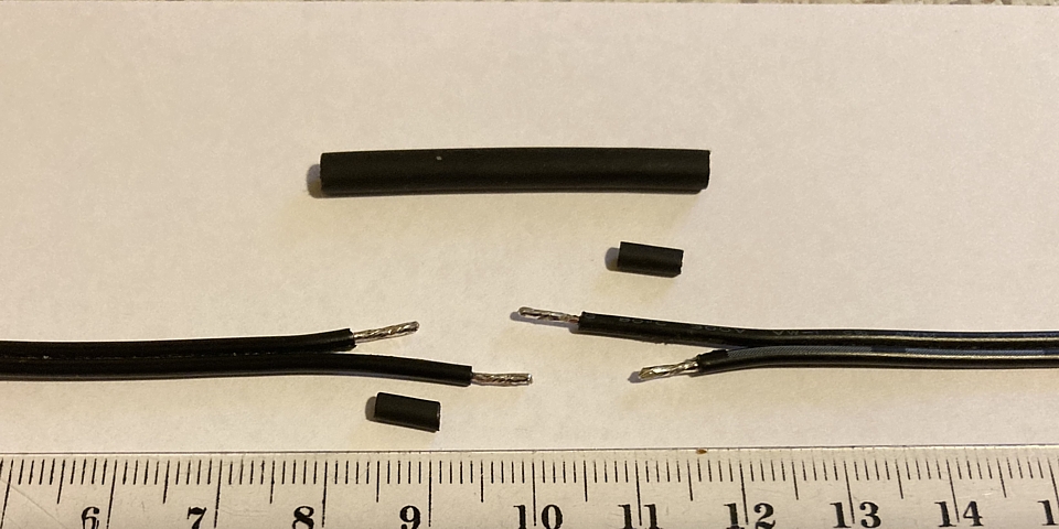
Slide the larger piece of heatshrink onto the cable far enough to prevent it from being heated during soldering then place one small piece of heatshrink on the longer section of wire before soldering the tinned wires together (quickly to avoid shrinking the tubing) and repeat for the other side.
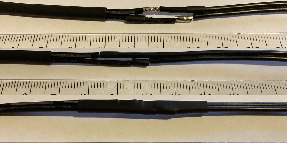
Once soldered neatly slide the small heatshrink tubing to cover the soldered joints and heat, followed by the larger tubing to cover the entire area. Staggering the two wire joins slightly results in a neater appearance and makes it impossible for the soldered wires to short together.
Getting back to the PCB, I'm also replacing the 3 pin headers for power and normal / inverse video with tiny, SPDT slide switches (Jaycar Part No. SS0834). These switches are rated to 0.5A at 12V so I've double checked the total current drawn by the computer which is only about 250 mA.
At this stage I'm not planning to power any major accessories via the expansion connector so the switch should be fine to replace the power header and will usually just be left in the default 'On ' position. Once a case is fitted both switches will only be accessable by removing the lid - the original ZX80 had no power switch and just ran when the power supply was plugged in.
The final components to be fitted to the PCB were C13 and C14 which form part of the 'Mic' record output for the cassette interface. I've also changed C15 from its original value of 220 pF to 47pF - this capacitor is part of the 6.5MHz oscillator circuit and 220pF is best suited to an original style ceramic resonator while I've used a low profile quartz crystal instead.
Although the oscillator was working with the 220pF capacitor the level of the 6.5MHz signal in the oscillator feedback loop was quite low, the 47pF value is better suited to the crystal and the levels within the oscillator section improved accordingly. That component change was recommended by Grant Searle who also substituted a 6.5MHz crystal for the ceramic resonator in his own ZX80 reproduction project, as detailed in the link below.
With the final components fitted to my Wilco ZX80 /81 PCB, it's time to test the computer with a more substantial program. Although the original ZX80 had incredibly limited resources and virtually no graphics capability a number of clever programming tricks allowed some flicker free graphics to be produced.
Combined with a 16k RAM expansion some of the programs which have been written for, or ported to the ZX80 are truly impressive. There are a few web sites which feature games and other software for the ZX80, most are in .o or .p format which can be used with an emulator or converted to .wav (audio) format to be loaded into an actual machine via cassette interface.
I'll try a file from the qrp.gr site (see links below) which has already been converted to .wav format. In recent experiments loading .wav files into my Ohio Superboard II reproduction, without first recording to tape I found that simply copying the file to an older model smartphone (with earphone socket) allowed the file to be played directly into the computer's cassette input with excellent results.
Repeating that process with the file for the ZX80 unfortunately did not work at all and I suspect there may have been insufficient signal level for the ZX80 cassette interface. Comparing the cassette input circuit of the two computers, the Superboard has an analog op-amp IC configured as a comparator along with two diodes 'back to back' to square up the signal from tape and increase the level to a 5V 'square' waveform.
The ZX80 on the other hand takes the input signal via a resistor, capacitor and load resistor - directly into (you guessed it) the input of another TTL IC. So the audio signal from cassette (or digital player in this case) must have sufficient level to be detected as a TTL signal, a few Volts at least.
Trying again, this time using my laptop to play the file via its headphone socket (at Max. volume) gives the desired result. The game has loaded successfully and begins to run. Fantastic!
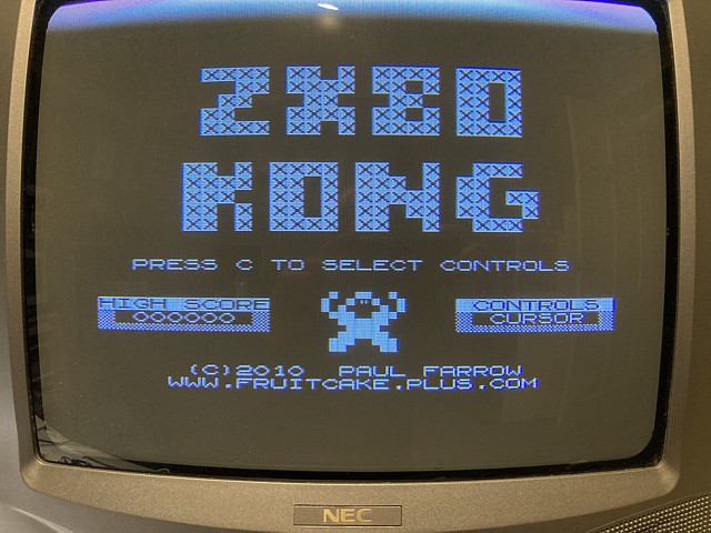
To see a faithful rendition of this game, along with other arcade ports running on such minimal hardware is astounding and a credit to the programmers, in this case Paul Farrow. Respect!
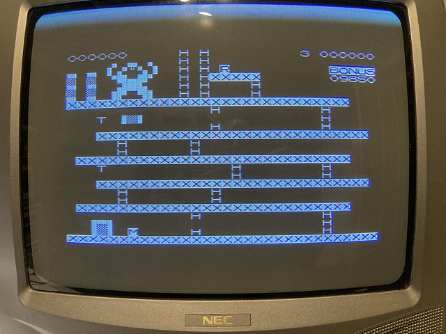
A YouTube clip of the game being expertly played on an actual ZX80 computer can be seen in the link below.
The Wilco2009 ZX80 / 81 PCB is assembled and working, Now to look the part, the PCB needs a replica ZX80 case!
From a performance point of view the ZX80 was unremarkable, even at the time far more capable home computers were available. What stood out was its low price, achieved by a design philosophy which excluded every component or feature which was not absolutely necessary for function. It was that minimalist design which set it apart and the ZX80s white plastic, clamshell case combined with blue membrane 'keys' became an icon.
Visually, it was unlike any other computer before or since. One prominent feature was a large bulge at the rear centre section of the lid which gave the product a purposeful appearance - it somehow reminded me of the 'power bulges' or bonnet scoops which were distinguishing features of many '70s muscle cars. Who can forget the massive reverse bonnet scoop which appeared on the A9X Torana? Similar appendages featured on General Motors' U.S. models; Corvette, Pontiac Firebird.
Of course in the case of the ZX80 the reality was far more mundane. Instead of concealing some performance enhancing feature the bulge was to provide clearance for the RF modulator; an off the shelf component which was enclosed in a large rectangular tin can. Although the modulator is no longer used in the Wilco version and the bulge could simply be omitted from the case design, the intention here is to make a replica case which resembles the original ZX80 as closely as possible.
Early production ZX80 cases were apparently vacuum formed while later units were injection moulded. There were slight variations in shape and dimensions but both versions are notoriously thin, fragile, have become brittle and often quite yellowed with age. For low volume production the setup cost for injection moulding is prohibitive, with enough demand a vacuum formed reproduction may be viable but for one-off applications the obvious alternative is a 3D printed case.
My own foray into 3D printing has so far been focused on designing and printing small components such as mounting brackets and a few moderately sized project enclosures which fit within the capability and build area of my FDM type 3D printer, using ABS filament. To date I've avoided complex structures which require additional supports to print, concentrating on designs which can be printed with each layer providing adequate support for the next.
For a new design these attributes can often be included to create a 'printer friendly' object but to replicate an existing product which was originally designed for a different manufacturing process is not always so simple. Apart from that consideration I don't have access to an original unit to measure exact dimensions so designing a case from scratch which adequately resembles the original seems overly ambitious.
Thankfully, a number of 3D printed replicas have already been produced, using dimensions taken from original machines. Hopefully I will be able to print an existing design or at least use the shape as a starting point for a reworked model rather than beginning from scratch. The first, by Alvaroalea on thingiverse.com (link below) looks terrific and is recommended in the Wilco2009 documentation so I know the PCB will fit the case.
My initial concerns are; no matter how the parts are placed on the build platform almost the entire structure will require substantial printed supports. Also, the base part being longer than my printer's build area will need to be printed in two parts which can be joined together post print.
I'll begin with the lid which is the most recognisable part, as the base is largely unseen from a normal operator's perspective I may consider drawing up a 'printer friendly' alternative base if printing the original style design becomes too hard. Looking at the lid model, the Alvaroalea design does include some thin internal walls which appear to support the base of the 'bulge' section but the rest of the surfaces would still need additional support.
There is a slightly reworked version by Cees Meijer on printables.com which may have increased thickness and is drawn without the internal walls - it occurs to me if that part was printed 'on edge' with its back facing the build platform it may only require support between the platform and back face, the rest being vertical or steeply angled may print without any additional support.
If the flange at the rear of the lid section is removed, at least temporarily the entire part may be printable with no additional support. Let's try that to begin with on my 3D printer and see how it goes. A small edit to the 3D object truncates it at the back face, I'll also add a row of ventilation holes along the back of the 'bulge' area - the original ZX80 was notorious for overheating as its case had no real provision for ventilation.
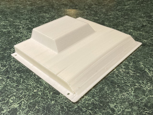
So how did it go? Well, it did print without collapsing entirely and the shape is roughly right but there are several issues. The most noticeable and disappointing one is some warpage and cracks between layers (delamination) in the mid print area. The cause of this would be uneven shrinkage due to cooling of the object during printing. Although the platform is heated and the printer build area fully enclosed, the object being quite tall would cool in the centre, further from the heated platform and extruder.
That seems to make printing the lid 'on edge' impractical, at least with ABS filament which does have a high shrinkage rate. Perhaps the result would be better using PLA filament, otherwise the best alternative would be to return the lid to a horizontal placement and go with additional supports. Even without support however this part took over 6 hours to print, using 20+ metres of filament. With supports I'd guess those amounts would easily double and most likely even more for the base.
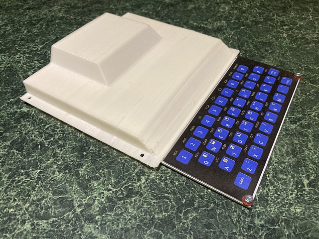
Here I'm resting the lid on the PCB to check its overall fit. Ive repaired the cracks as well as possible, using some baking soda and super glue just to prevent the lid from breaking in two. Looking at the rear, I had to file the original opening to fit the DC barrel connector so I think it would be better just to remove that and refit an original style 3.5mm jack, also swapping the plug on my power supply (again!)
Those added ventilation holes should help with cooling but do look like an afterthought. The Wilco PCB doesn't appear to run as hot as the original reputedly did, probably as the major current draws and heat sources were the original RAM, EPROM and CPU which have been replaced with modern low power components. I'm still using an original style NMOS Z80 CPU but with the CMOS RAM and EPROM and a proper heatsink for the 5V regulator the board doesn't seem excessively warm.
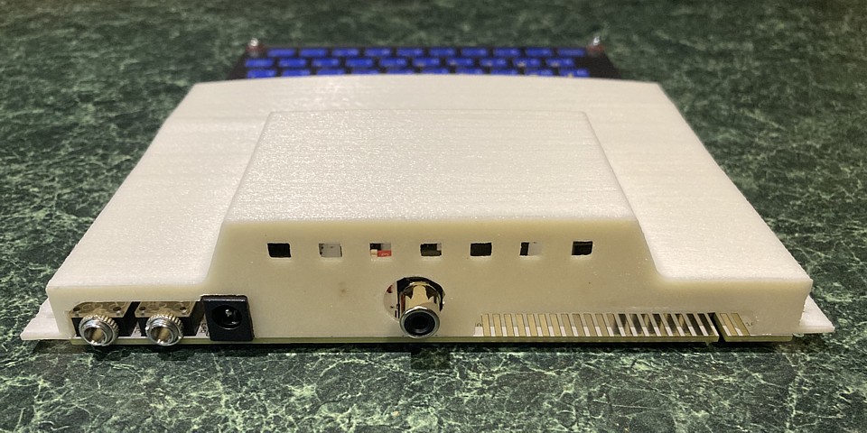
At this point it seems that 3D printing the case with my current setup isn't really viable. The finish on the original part is not good enough and would require extensive sanding, filling then painting whereas I was aiming for a reasonable finish from the original material. So at the very least I would need to swap from the 'natural' colour ABS to white PLA, also using a lot of material printing additional supports and the base section would still need to be printed in two parts.
Looking for better solutions, an SLA printer which uses a laser to set a resin rather than an extruded filament, can provide a much smoother finish and finer detail but no hobbyist type SLA printer would have the build capacity to produce these parts. An industrial SLA printer on the other hand may be able and give better results than even the best FDM type 3D printer.
I've never considered ordering 3D prints of an object before but it seems worthwhile obtianing a quote to have these parts SLA printed. As it happens the same manufacturer who produced the PCB also offers 3D printing solutions so I'll give them a try. The objects I've requested a quotation for are unchanged from the originals apart from error checking, correcting some minor issues with the 3D meshes and re exporting the .stl files.
The initial quote seems very reasonable but there were a number of issues pointed out regarding the thickness of the parts in several areas as well as a general caution about printing large, flat, thin objects without additional strengthening ribs etc. That's not surprising as these items were designed to look exactly like original parts and not specifically for SLA 3D printing.
Although I was advised that there was a high risk of the items being broken or deformed during printing I thought the best way to proceed was to go ahead with the initial set of prints then address any issues with broken or deformed parts by redrawing the objects to increase the thickness or add strengthening where required. To my amazement, both the full sized base and lid printed perfectly without alteration. Absolutely fantastic!
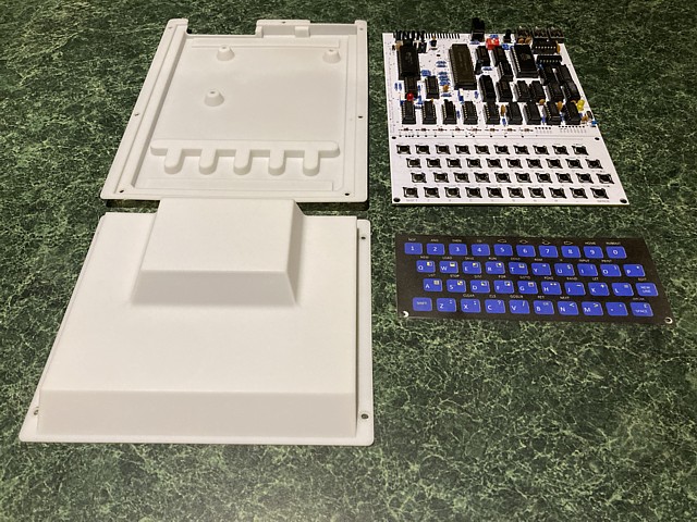
I may have just been lucky and the results may not be repeatable without addressing those issues but I couldn't be happier with the fit and finish of these parts. A third part, which was just the back section of the 2 part base which I had included for comparison did suffer a broken flange and some warping at the point where it would join the other part. The join is effectively a cross section without the raised perimeter frame to add any rigidity so that smaller part proved to be unsuitable for SLA printing.
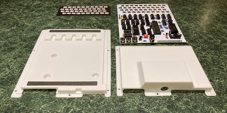
The full sized base which was from the Alvaroalea set was drawn without holes so here I have placed the PCB in position to mark the 5 mounting hole centres then placed the lid (which was from the Cees Meijer set, both files with no included supports) over the base to mark the 5 lid securing hole centres. After that I carefully drilled the 10 holes, starting at 1mm and working up to 3.3mm to provide sufficient clearance for 3mm screws and hopefully avoid any additional stress due to misaligned holes.
I'm placing 3mm fibre washers under the keyboard overlay just to space it up to the level of the dome switches, also at the 3 PCB mounting holes. On the underside of the base there are two grooves for rubber feet, I've cut 2 strips from a small sheet of self adhesive foam rubber, 9mm x 125mm to fit neatly into the grooves which will hopefully provide a stable base as well as avoid scuffing the smooth, 3D printed surface.
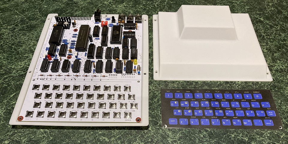
The original ZX80 was held together with small plastic rivets which I believe are still available but I'm not sure if the rivets, which are fixed in place by expanding their stem would add to the risk of cracking the case flange. I think some 3mm, socket button head screws and nuts would be a better choice and provide a similar appearance - with a lick of paint.

No build or restoration thread seems complete without 'The Painting of the Screws' so here they are, white for the lid and a couple in black for fixing the keyboard overlay.

A couple of labels for effect and the replica is complete. I'm not attempting to pass it off as an original unit so the labels and keyboard overlay don't need to exactly match the original finish. From a nostalgia point of view all of the elements are present.
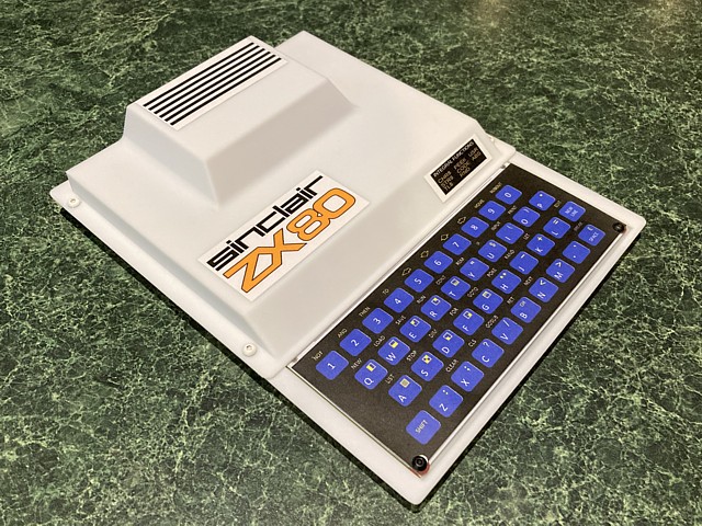
The 3D printed case is better than I ever expected and probably cost no more than the materials I would have needed to attempt to print it on my own FDM machine. My sincere thanks to Alvaroalea and Cees Meijer for their designs. In the course of searching I also found a separate ZX80 Replica Case 3D project by Spinnetti on printables.com which recreates the vacuum formed version of the original unit. Although I didn't attempt to print those files the design also looks excellent.
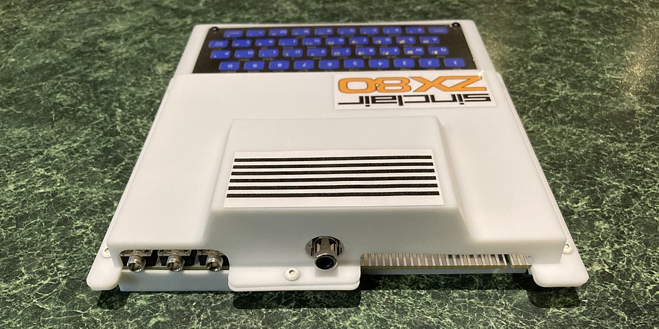
The finished computer, fully working and power supply (repurposed from an old ADSL router). It will probably end up in my display case but just to protect it from any damage when not in use I'll even give it a box.
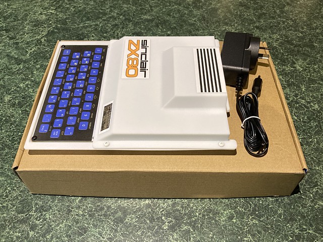
I'm not sure if anyone else does this, but these die-cut cardboard boxes which come with everything from PC motherboards to PCB and 3D printing orders can be unfolded and reversed to give a new appearance to a repurposed package. On the inside their origin is revealed...
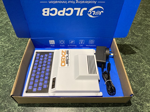
More projects and repairs to follow soon...
Sinclair ZX80 (original) specifications
| Made | From 1980 - 1981 |
| CPU | Zilog or compatible Z80A @ 3.25 MHz |
| RAM | 1 kByte, including video RAM (expandable to 16 kByte) |
| FDD | None |
| Ports | Cassette, Expansion (46 way, 44 contact card edge connector) |
| O/S | Sinclair 4k BASIC in ROM |
| Display | Monochrome, 32 x 24 characters displayed |
| Sound | None |
| Monitor | Monochrome TV RF only |
| Keyboard | On board, membrane 40 keys |
| Speakers | None |
Web Resources (External Links) -
Wilco2009 /zx80-81-Double-Clone - github.com
Grant's Sinclair ZX80 Homebuilt hardware page
Sinclair ZX80 Case - Alvaroalea, Thingiverse
Sinclair ZX80 Replica - Cees Meijer, Printables
Sinclair ZX80 Replica Case - Spinnetti, Printables
Can You Build A Brand New ZX80/81 From 100% New Parts? - the Retro Shack, YouTube
Flicker-Free Kong (16K ZX80) - ZXFruitcake, YouTube
Sinclair ZX Resource Centre - www.fruitcake.plus.com
ZX80 Software page - qrp.gr/zx80/software.htm
About the ZX80 / ZX81 - sinclairzxworld.com
ZX80 - Centre for Computing History
All images and text on this website are Copyright.
Contact: jbtech at telstra dot com