Meteor (Asteroids clone) PCB repair
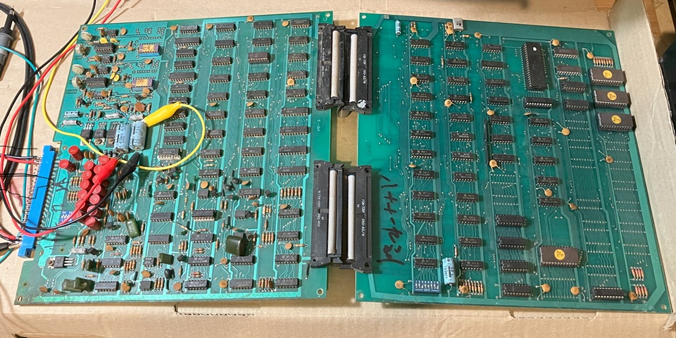
Here I have a Meteor PCB set by Hoei Intl. on the bench for testing and repair. It appears to be an almost exact copy of the Atari original. Although the layout appears virtually the same there is one notable difference; the Meteor circuit is divided into two halves connected by a pair of ribbon cables whereas Asteroids employs a larger single PCB.
The Meteor PCBs aren't in great condition with some corroded IC legs and messy traces of previous repairs. Checking for any damaged or broken components I have noticed one issue - there is a row of inductors with plastic housings near the edge connector and the outer ones have been pushed over breaking their connecting leads.
There don't appear to be any circuit diagrams available specifically for Meteor so I'll refer to the very comprehensive Asteroids documentation and note any differences encountered. In the circuit extract below the 13 x 100 uH (microHenry) inductors are shown in line with the input signals with capacitors to ground forming a low pass filter arrangement. There is another pair of inductors nearby on the PCB, in series with the X and Y vector outputs.

I'm not sure whether the input and output filtering was primarily intended to reduce glitching and switch bouncing of the controls, or to suppress any RF interference generated by the circuit to meet FCC standards - it may have been effective in both regards. Although the inductors specified for Asteroids were 100 uH the ones fitted to meteor are marked 102 which would correspond to 1000 uH (or 1 mH) as I have confirmed by measuring one out of circuit with my multimeter.
Fortunately the ones with the broken leads have just enough of a stub remaining to solder into the PCB so I have swapped these two to the X and Y output positions for the moment. I'll try and source some new replacements with my next parts order. So the next step is to begin making up a test lead, set up power supplies and check for circuit activity.
I'm setting up a Meteor arcade PCB set for testing on the bench, beginning with connections for power only. I'm not connecting a monitor as yet, in fact I don't have a vector monitor to work with this game so will just use a Cathode Ray Oscilloscope set to X-Y mode and the Z input (which is available on the rear panel of the CRO) will control the beam intensity / blanking of the vector signals.
There is a 2 x 22 way edge connector for power and signal connections which appears to be pin compatible with Asteroids, I'll trace and confirm each connection with my multimeter just to be certain. Initially I'm just wiring up the +5V logic supply using a basic arcade switchmode PSU, the only other power connection required is 36 Volts AC (centre tapped) which is then rectified and regulated on board to provide the remaining DC Voltages required by the circuit.
I also don't have a transformer with a 36V secondary handy so will substitute an equivaent DC Voltage to the point on the PCB after the rectifier stage.But first I'll test the 4 diodes of the bridge rectifier with my multimeter to confirm none are shorted or open circuit and the correct forward Voltage shows on my meter display for each diode. Having done that I'll connect my bench power supply to the inputs of the on-board regulators at the smoothing capacitors C87 and C86.
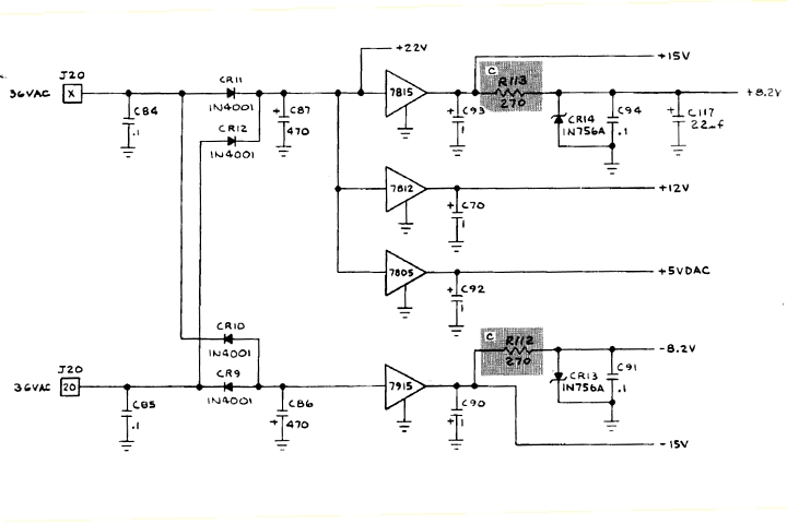
My bench power supply can manage plus and minus 20V DC at up to 3 Amps which should give enough headroom for the +/- 15V regulators to work correctly. I notice the circuit diagram indicates a nominal +22V at C87 and one would assume a similar negative amount at C86, also allowing for the forward Voltage drop across diodes and some AC ripple.
With the Voltages set on the bench power supply (+/-20V) and arcade PSU (+5V), powering on briefly to measure the regulated supplies on board the -15, +12 and the separate +5V supply (for the digital to analog converters) are present and correct but the +15V is missing. Power off, testing for a short to ground across the +15V rail does not reveal any problem so I suspect the 7815 regulator IC is most likely at fault.
That's a locally available part so after sourcing a couple of spares and replacing the IC in question, powering on once again the +15V rail is restored - but the zener diode regulated +8.2V rail now reads just over 10V so that diode must be open circuit. I don't have that value on hand so will try to source one locally and replace that component before powering on again.
I'm just getting back to this Meteor arcade PCB repair as I have been juggling a few works in progress of late. So far I have identified a faulty 7815 regulator IC and 8.2V Zener diode in the on board power supply regulator stage. Having replaced both of those all of the internal power supply rails are now present and correct. The next step will be to check for activity on the X and Y vector outputs in the unlikely event that the rest of the PCB is working correctly.
No joy there, both vector outputs show no sign of life when viewed with my oscilloscope so I'll check for activity further back, beginning with the signals at the 6502 CPU. If a board seems 'dead' with no output activity the usual starting point for troubleshooting is to check the CPU power, clock and reset lines followed by address, data and then control signals to see whether the CPU is active or idle, perhaps in a wait state or some sort of reset loop.
In this case there does seem to be some activity but the CPU reset input pin 40 is toggling so the CPU is repeatedly being reset, presumably by the watchdog timer. Many arcade PCBs especially those based on Atari designs include a watchdog timer to reset the CPU if the intended program flow is interrupted for whatever reason e.g. a power glitch, software bug or hardware issue.
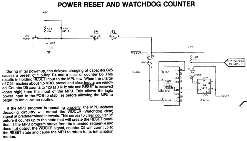
If the cause of the issue was a one-off glitch then normal operation will automatically resume after reset but a more serious fault will cause the watchdog timer to reset the circuit repeatedly, as is happening in this instance. The Watchdog timer is exactly that, a counter which will cause a CPU reset after a certain delay. In normal operation the timer must be accessed by the CPU program at regular intervals to restart its count. If that does not occur the timer will reach its limit and trigger a CPU reset.
Interestingly the reset signal in this case is not repeating at a steady, regular pace but with varying intervals which suggests the program is operating to some extent and clearing the watchdog timer initially but stalls at some point allowing the watchdog timer to reset the CPU and the cycle then repeats. The most likely cause of a CPU which begins to run but ends up in a short reset loop would be a ROM or RAM fault so I'll try to verify those components out of circuit to begin with.
Fortunately both ROM and RAM are socketed on this PCB. The four MB8516 EPROMS are labelled ME1 to ME4, they're 2716 equivalents so can be read with my EPROM programmer and verified against known MAME ROM sets using an online ROMident utility. Having done that all 4 are exact matches to known ROM files, two are identical to Asteroids ROMs while the other two match up with an Asteroids clone called Aerolitos.
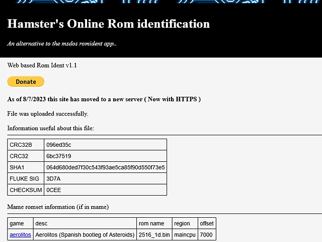
Incidentally, there is a known ROMset in MAME for Meteor by Hoei Intl. but that set is read from 8 x 1 k Byte ROMs whereas this PCB is fitted with 4 x 2k Byte EPROMs. The easiest way to directly compare this version to that known set would be to first divide each of the 2k Byte files in half. As there is a relevant match for the existing 2k Byte EPROMs there is no need to take that extra step, the EPROMs and their contents must be working correctly.
Next testing the 6 x 2114 static RAM ICs using my CPU / RAM tester, two of the vector RAM ICs fail the tests with data errors. Fortunately I still have a few spare 2114 ICs on hand so I'll place the 4 ICs which passed the RAM tests into the vector RAM positions and the two replacement ICs (which are also tested and working) into the CPU RAM positions on the PCB.
That done and powering on once again there is a definite improvement with the CPU reset line now remaining high after initial reset so the program seems to be running without crashing. Checking the vector outputs once again there is a repetitive short burst of signal on the X axis but just some noise on the Y vector output. At this stage there is no point viewing those signals in X-Y mode so I will trace back from the Y vector output to see if i can find a point where that signal goes missing.
Continuing with the fault tracing on the Hoei Meteor PCB set; to date I have checked and repaired the DC power supply regulator stages, replaced a couple of faulty 2114 RAM ICs and resoldered two inductors which had broken leads. When the circuit is powered on I am now seeing a repetitive, short burst of activity on the X vector output but only some low amplitude noise on the Y output.
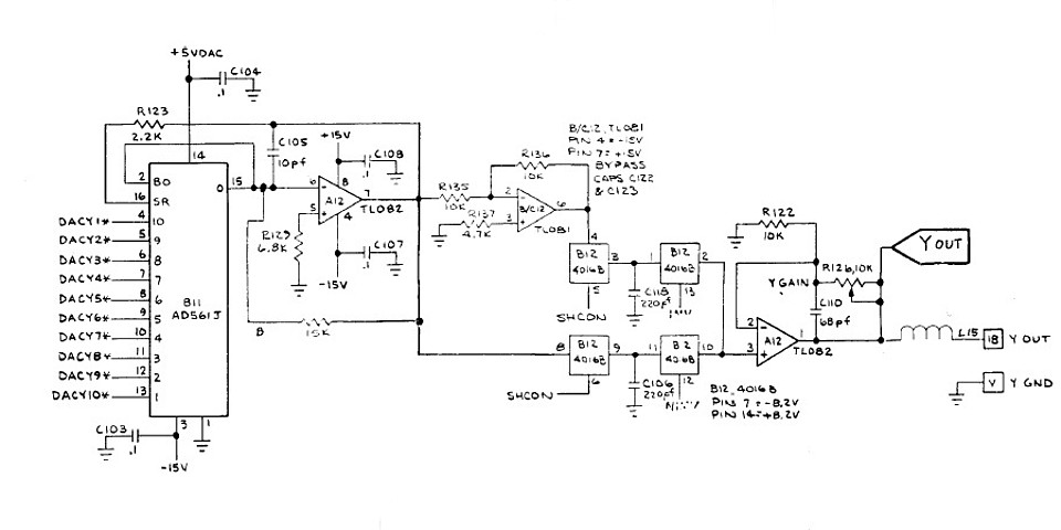
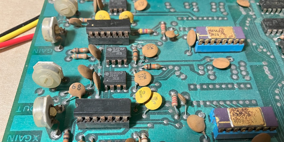
Referring to the (Asteroids) circuit diagram once again, the Meteor output stages appear very similar and the good news is there does appear to be some activity at the output of the Digital to Analog Converter. Following that is a CMOS analog switch, in this instance a 4066 IC is used rather than the 4016B shown in the circuit diagram.
Checking its outputs there appears to be just some DC offset with no signal activity, it could be the IC itself which has failed or a poor connection due to severe corrosion of its pins. It's not just a bit of surface rust, the IC legs seem to be almost rusted through and the IC socket appears to be similarly affected. I have some 4066 ICs to hand so will replace this one as well as the IC socket.
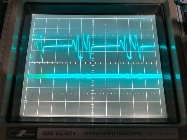
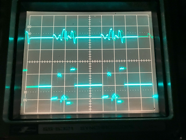
The corresponding IC on the X vector output stage doesn't look much better so I will also replace that one in due course but for the sake of fault tracing will leave well emough alone for now. So, after replacing the 4066 IC in position B12 along with its socket the X and Y vector outputs are now both showing little bursts of activity. Switching the Oscilloscope display to X-Y mode there is some sort of image:
As yet I haven't connected or even checked the Z (intensity) signal from the PCB so the entire path of the X / Y outputs are visible including a bright centre spot, not only where valid characters are present. To avoid phosphor burn I only turned the brightness up briefly and just enough to make the traces visible for the above photo.
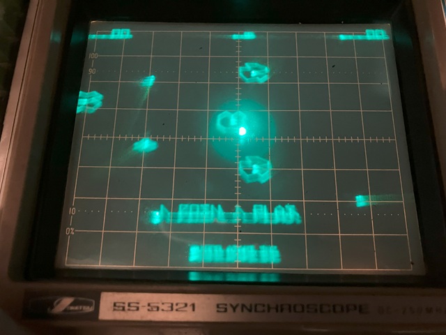
The image seems pretty indistinct so there may still be some graphics issues but the program appears to be running, in attract mode with the Asteroids - er, Meteors drifting around and some text message on screen. Switching back to 2 channel display the Y vector output now looks sharp, by comparison the X vector output appears low in amplitude as well as having a poor slew rate.
That could be an op-amp problem but I'll begin by replacing that second rusty 4066 IC and socket to see whether it resolves the issue: That done, the image now looks much better with some recognisable shapes and text. The next step will be to check and connect the PCBs Z output signal in order to see the displayed characters more clearly.
I'm making slow progress with the Hoei Meteor PCB repair; the game runs now in attract mode and I can see the vector graphics on my oscilloscope display in X-Y mode albeit not clearly as yet. To see the vector lines which make up the image without all of the intermediate traces (as the beam jumps from the completion of each line to the start of the next) I need to connect the PCBs Z axis (intensity) signal to the Z input on the rear panel of my oscilloscope.
The Z signal determines not only the blanking but also the relative intensity of the vectors which are to be displayed. Reading the Atari Asteroids circuit description, the blanking level of the Z Output is 0 Volts with +1 to +4 Volts for the range of intensity determined by the 4 bit SCALE signals, giving a possible 16 shades of grey (or green as viewed on the oscilloscope display).
So the Z output is effectively a positive video signal, with higher Voltages resulting in a higher display intensity. Checking my oscilloscope manual however a positive going signal on its Z input decreases intensity, to obtain a correct image I will need to invert the Z Out signal from the Meteor PCB.
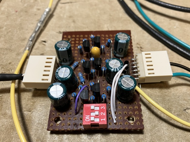
To achieve that I can use my video inverting amplifier which I originally built and used for testing a Nintendo Space Firebird PCB set. Since then I have used it for other Nintendo games from Space Fever to Donkey Kong as all of these titles originally used a Sanyo monitor which required a negative going video signal. The amplifier has 3 identical channels to invert an RGB signal
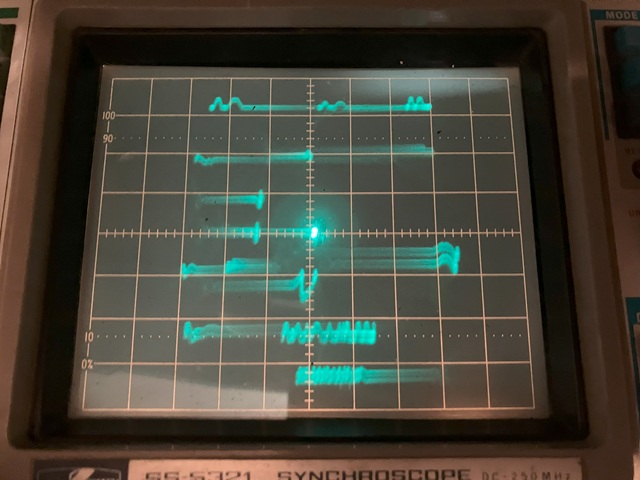
In this case I only need a single channel to invert the monochrome Z signal from the Meteor PCB and the input termination is not required but I will leave the 75 Ohm terminations switched on for the other two inputs so they are not left floating. Having done that the vector image on my oscilloscope display is much improved but still not perfect.
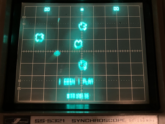
The main problem now appears to be an instability in the Y axis causing a blurry ghosting or double image vertically on the oscilloscope display. It's most noticeable on the text characters, I think this is a fault in the Y channel of the Meteor PCB rather than a problem with the test setup or general power supply issue which would most likely affect both X and Y axes equally. So I'll need to check for noise on the PCBs Y axis output.
To be continued...
Meteor / Asteroids specifications
| Made | 1979 |
| CPU | MOS Technology 6502 @ 1.512 MHz |
| RAM | 1k Byte program RAM plus 2k Bytes vector RAM |
| ROM | 6k Bytes program ROM plus 2k Bytes vector ROM |
Web Resources (External Links) -
Hamster's Online Rom identification
All images and text on this website are Copyright.
Contact: jbtech at telstra dot com