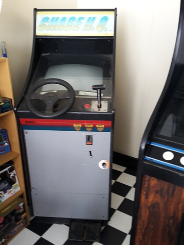
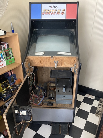
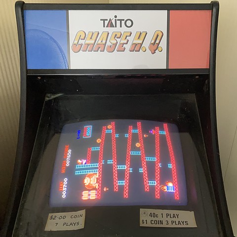
Gottlieb Lowboy driving cab, Chase H.Q. by Taito
This is the second Chase H.Q. Lowboy I have for repair, its cabinet appears to be locally made by Gottlieb Electronics who, despite their name apparently bore no relation to Pinball and Video Game manufacturer Gottlieb in the USA.
Although looking fairly intact externally some of the internal connections which had been soldered directly onto the PCB pins have been cut, suggesting the game PCBs had been disconnected for repairs and never returned to service.
It is complete nonetheless so I'm hoping it can be brought back to life. The first step is to remove the game PCB set and desolder the remains of the hard wired connections, clean up the PCB pins so it can be checked on the bench with a test cable.
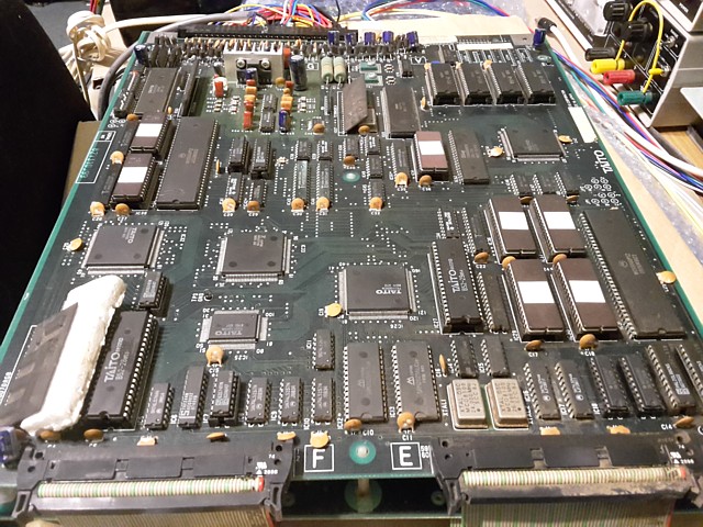
This is the second Chase H.Q. PCB set for repair, having been removed from the Gottlieb Lowboy driving cabinet. I hope to get it running but there's no guarantee, being a late 80's game it is much more complicated than earlier titles and also makes use of several 'custom' ICs for which replacements, if required may not be available.
The PCBs don't look as clean as the previous set and there's a bit of corrosion evident on some of the components. After a dust off with a soft brush and compressed air it's time to connect them up on the bench and see where we stand.
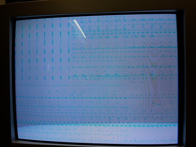
Powering up there's obviously a major fault but the news is not all bad, at least there is sync as the faint pattern which is visible on the screen is stationary and not rolling also the pattern does change and is not completely static so there is still some activity.
I've removed the second Chase H.Q. PCB set from its Gottlieb Lowboy cabinet and checked it on the bench using my JAMMA test lead which I've customised to suit the Chase H.Q. specific pinout. The game doesn't run, there's just some 'garbage' on screen which changes slightly every few seconds. Presumably a watchdog timer is resetting the main CPU when the program fails to run.
It's a pretty daunting repair with 3 CPUs on board (2 x 68000 and a Z80 just for sound) as well as a bunch of 'custom' ICs, some in surface mount packages of up to 160 pins. If one of those turns out to be faulty (with replacements most likely unavailable) the board would be a write-off, useful only for spare parts.
Fortunately, the other Chase H.Q. PCB set is now working (apart from a minor graphics issue) and will be a useful resource for troubleshooting this one. The first little shortcut will be to test each PCB separately, in conjunction with the other known working board.
Not surprisingly, when testing this CPU board with the working Video board the symptoms are unchanged. It's pretty obvious the main fault is on the CPU PCB. Testing the Video Board from this set with the working CPU board, there is an 'OBJECT RAM ERROR' on startup. That fault can wait until the CPU issues are resolved.
The next step is to remove the program EPROMs from their sockets on the CPU board, read them with my EPROM programmer and verify their checksums against known Chase H.Q. ROMsets listed in MAME. Having done that all the EPROMs verify correctly, matching the checksums for Chase H.Q. (Japan).
And removing each of the remaining socketed ICs in turn from the faulty CPU PCB and testing them in the otherwise working board, all are found to work correctly except for IC 27, one of the Chase H.Q. graphics ROMs which appears to cause a graphics issue. It looks like corroded pins on the IC could be contributing to that problem so hopefully cleaning the ICs legs will resolve that.
So far the results are good, none of the components tested as yet appear to be causing the major CPU fault. It's time to start looking at signals around the main CPU, the working PCB set may still be helpful here as a basis for comparison.
Beginning to probe each signal around the main CPU and adjoining components (bottom right of picture above) the Address and Data lines are all sitting at an intermediate level part of the time while the /Reset and /Halt lines are held low (the CPU outputs being in high impedance mode) then the reset and halt signals are released and the outputs all become either High or Low - but there is no activity, they all appear as static signals. The CPU clock is running, however. After a few seconds the /Reset and /Halt cycle repeats.
So the program has stalled for some reason. Looking around this part of the board I notice the two PAL ICs which are used as address decoders and the two 74LS245 buffers next to those are all running very warm. This could just be due to the outputs being stuck with no activity but the buffers also appear to be the components worst affected by corrosion on the whole PCB, the pins being quite rusty.
It seems this corner of the board which was closest to the incoming air from the cabinet fan was the worst affected by dirt and moisture so I'll start by replacing the two buffer ICs with new ones, also adding sockets. In the picture above these have just been done. Powering on again, that hasn't cured the main fault but was worthwhile fixing this obvious issue in any case.
Probing the signals around the two PAL ICs at extreme bottom right of photo above which are also running very warm, most appear as static levels again except one on IC21 which appears to be floating. According to the circuit diagram it's supposed to connect with the Taito custom IC26 but I can't measure any continuity. Tracing the PCB tracks visually and with a meter it appears track rot may have set in.
Track rot is corrosion of the PCB tracks themselves which occurs when moisture or contaminants penetrate below the green PCB mask and attack the copper. PCBs such as these with high density components and ultra fine copper tracks are obviously most prone. The solution is fairly simple, adding a 'jumper' using some fine wire-wrap style insulated wire to bypass the affected track but the issue could crop up on many tracks in seemingly random locations.
On the bright side, it's easier repairing a damaged track with a bit of wire than replacing an obsolete component which is unobtainable so I'll keep going and hope I don't reach a dead end at some point. Having sorted that first track problem the signal is now present at the PAL IC but once again the fault symptoms are unchanged. At least now I have a clue to potential further problems in this section of the PCB.
The Gottlieb Lowboy driving cab had taken a back seat for a while, its Chase H.Q. PCB badly affected by track rot and quite a bit of time having already been spent on it without much progress.
The worst affected area seemed to be the corner of the PCB nearest the main CPU so I started there, checking each pin of the PAL ICs (used as address decoders) and buffers on the circuit diagram to see where they were supposed to connect then testing with a multimeter to see if that connection was OK.
Having found a dozen or so connections with no continuity and adding wire links to correct those the symptoms were still much the same, only a slight variation in the patterns on screen but seemingly no closer to locating the main problem.
I would have been inclined to keep plugging away at it indefinitely but fortunately was offered a complete and working Chase H.Q. PCB set. That was a real lifeline as there was no guarantee the existing PCBs could be fixed at all, if one of the surface mount custom ICs was faulty or pins corroded beyond repair for example.
I may still revisit the repair attempt on the previous PCB (if time ever permits) otherwise will just keep it for spares. Having tested the 'new' PCB set on the bench and confirmed all functions are working we can skip to checking and repairing the rest of the components and wiring in the lowboy driving cabinet.
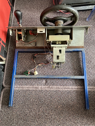
So to begin with I'll open up the cabinet and clean out some of the old dust and dirt with a brush and vacuum cleaner. After unplugging the control wiring harness and releasing a number of clips the control panel hinges open, slides out and comes away completely, making the task a bit easier.
 |
 |
The first and most important major component to check is the monitor with Kaga KZ-20EN chassis and Mitsubishi CRT. Using my portable test setup to run the monitor independantly of the rest of the machine I get nothing - it seems there may be a problem in the Horizontal output / EHT area of the monitor chassis.
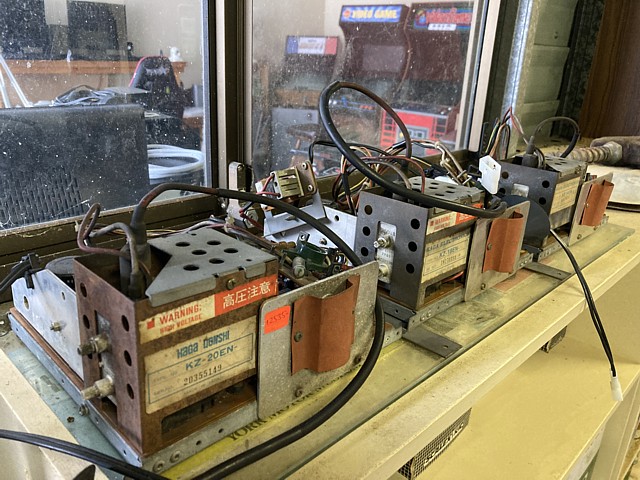
Out it comes, waiting its turn on the 'to be fixed' shelf. Meanwhile, here's one which I repaired earlier.
 |
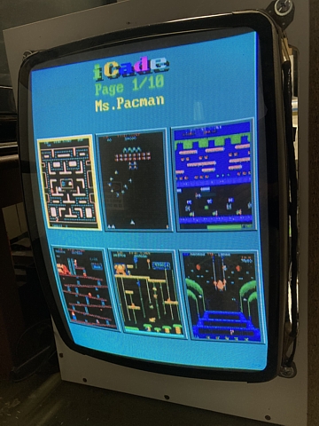 |
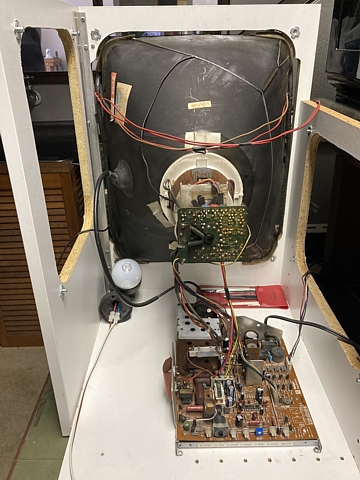
This one is a similar model and had an issue with the Vertical deflection, seen here running well on the test bench so the next step is to install it into the machine, pair it with the machines original Mitsubishi CRT and see if there's any life left in that.
Fortunately it's a good tube with a clear image, no major purity or convergence issues or noticeable burn in. That's the first part of this machine so far which was still working when tested.
To be continued...
Web Resources (External Links) -
The Arcade Flyer Archive - Video Game Flyers: Chase H.Q., Taito
Hamster's Online Rom identification
All images and text on this website are Copyright.
Contact: jbtech at telstra dot com