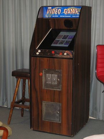
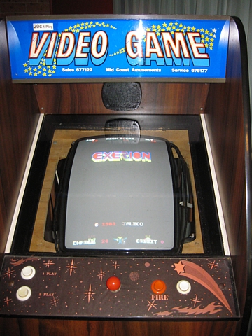
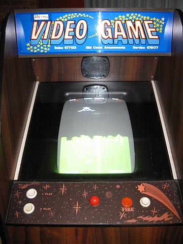
Autorec Arcade Machine
Purchased as an unbranded '80s Arcade Machine, now believed to be a rare survivor manufactured by AUTOREC in Springwood, Queensland.
Although the original game PCB and CRT monitor had been replaced by a multigame board and LCD the unit retains its original 80's woodgrain finish and single player control panel.
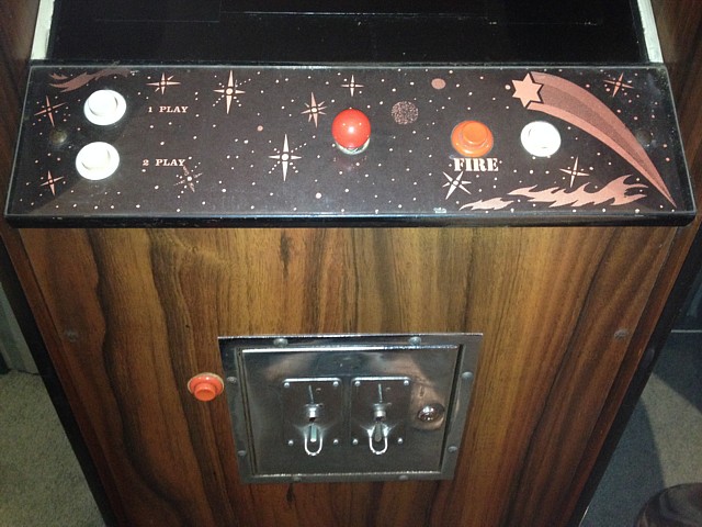
The original Asahi Seiko coin mechs were not connected and were missing some moving parts so I have replaced them with a pair of Coin Controls S-1 mechanisms which fit the cutouts in the original coin door, one set to accept 10c and the other 20c coins
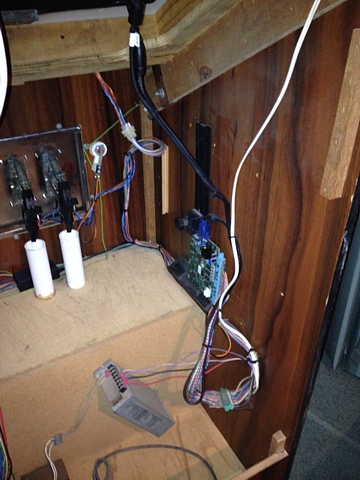
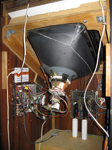
The inside of the cabinet seems vast with an LCD monitor instead of the CRT. I'm inclined to convert it back, if I can find a tube of the correct size in good condition. The mounting panel is still present, visible in this photo.
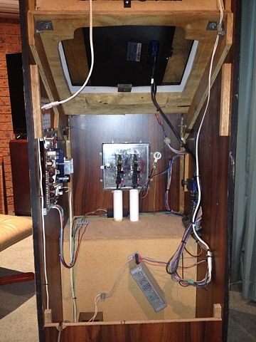
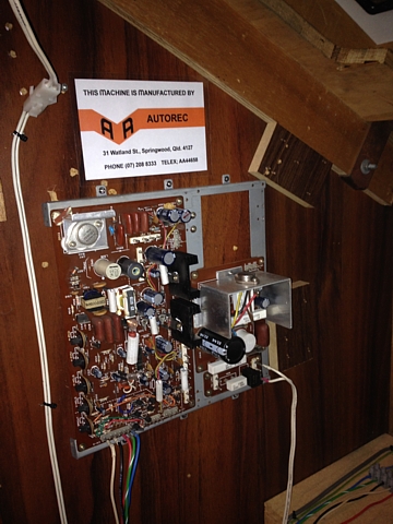
The CRT monitor chassis is also still present though currently unused, minus its line output stage and was (amazingly) still connected to the power when first tested! There is a number written on the edge of the bottom panel which I suspect is a build number or serial number.
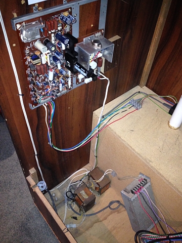
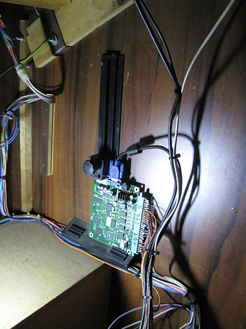
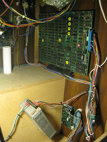
Where the original game boards were fitted (it may have had many different ones over the years) the PCB bracket is still there. It currently holds the tiny multigame PCB, connected via a JAMMA adapter harness. I'd also like to install a dedicated game PCB from the era here, relocating the multi game board and retaining it as a 'backup' unit so that either can be plugged in to the cabinet wiring and played.
To save the machine from obscurity I've printed up and laminated a reproduction of the manufacturer's label which I found in photos of a nearly identical cabinet online. It's not made to look old and original but the details are otherwise as close as possible.
Although this machine has been reliable, having been 'upgraded' with a Multigame PCB and LCD monitor and playing most of my favourite 'Golden Age' arcade games it's just not the same as an original machine running a game on original hardware with a period-correct CRT monitor.
This is a genuine '80s arcade machine after all and deserves to be 'un-graded' back to its original specification or as close as possible. To that end I've purchased a few suitable bits and pieces whenever they have become available at a reasonable price and nearby enough to inspect and collect the items in person.
I've managed to source a number of original arcade CRTs and chassis, all 'fixable' or working to some extent which I'll overhaul and select the least worn 51cm (20") CRT to go back into the Autorec cabinet.
That's a project which will take some time, meanwhile I have also purchased a couple of non-working 80's arcade game PCBs to hopefully repair and install as well (the existing multi game PCB can also be used with a standard resolution CRT monitor though it is currently set for VGA output to suit the LCD).
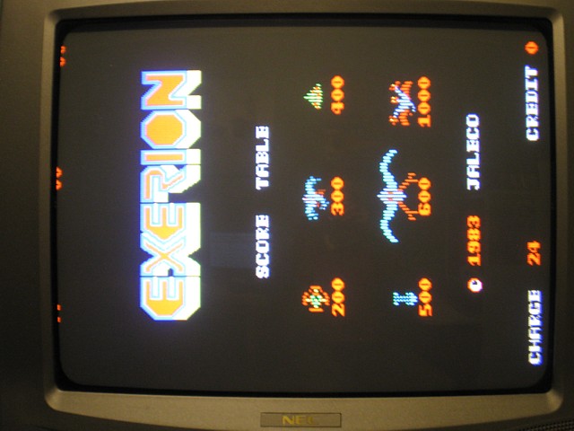
The game I've found which will suit this machine very well is 'Exerion' by Jaleco from 1983. A lesser known title from a minor player in the Videogame industry, it seems perfectly matched to this low-volume production arcade machine from an obscure Australian manufacturer, Autorec.
It's technically suited to the cabinet, requiring a vertically oriented colour monitor, 8 way joystick and two buttons, perfect! And it's interesting to play with its semi 3D perspective and other-worldly colours. It will be the exact sort of setup you might have played mid '80s while you waited for your Fish 'n Chips or Burger with the lot at your local Take-away.
The game runs on a single PCB with pre-JAMMA interface. I've bought two of them to improve my chances of fixing at least one but the intention is not to rob one board to fix the other, I'll be trying to get both boards working if at all possible.
One of the boards looks complete while the other is missing some ROMs as well as one or two of the smaller ICs - that one will be my 'backup' PCB. They both have had some obvious repairs done in the past with a few wire links added, presumably to mend damaged tracks but I'll leave those until I have at least checked the current status of the boards.
I'm putting the incomplete PCB aside for the moment and won't do any testing on that one until I have first replaced any missing parts. There is also one issue on my 'primary' board which must be corrected before I can power it up and test it.
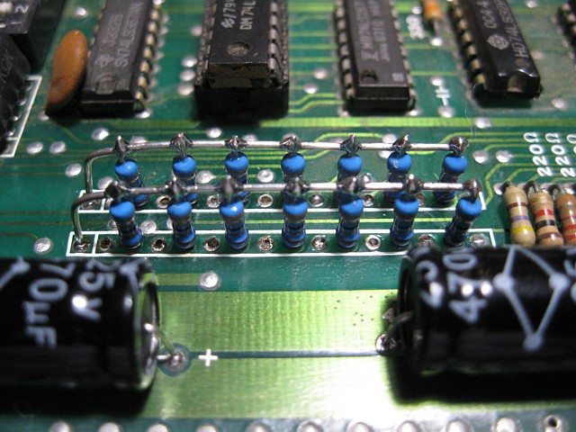
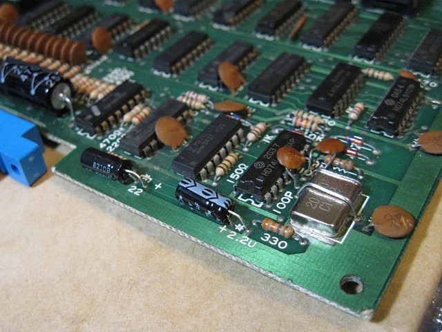
It looks like there was originally a pair of resistor arrays connected to the control inputs which contained a series resistor as well as a pullup resistor for each input. At the time they were probably custom manufactured as I've never seen a resistor array with that arrangement all in one package.
At some point they have either failed or a circuit revision called for a change in the component values so these have been replaced with a bunch of conventional resistors with the pullup resistors 'piggy backed' onto the series resistors. It's all a bit overcrowded and some of the pullup resistors have broken loose at some stage. Eeeeeek!
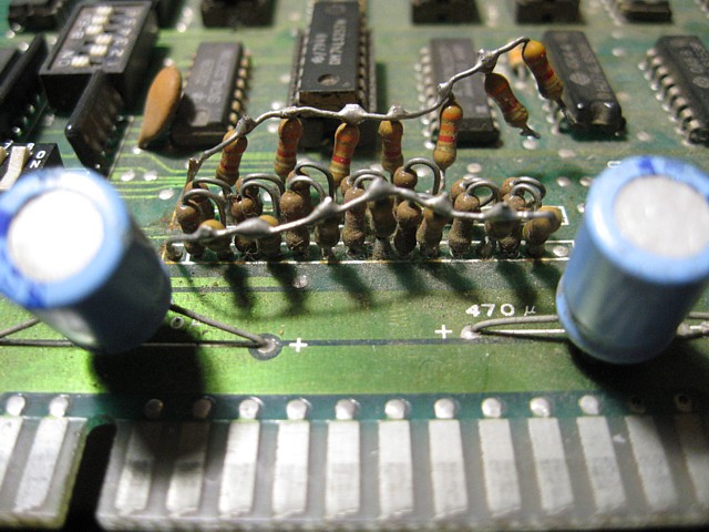
I've no hope of finding a suitable resistor array to put back in so my next best option is to remove this lot, starting anew and install one end of the 'pullup' resistors into the relevant PCB holes, still linking them to the positive rail with a wire across the top then add surface mount 'series' resistors between the appropriate PCB pads on the bottom 'solder side' of the PCB which should be much neater and less prone to breakage.
I only use surface mount components when necessary so I'll have to order these, in a couple package sizes so I can select the largest (= highest power rating) which will fit the pad spacing. While I'm at it I will order some Axial Electrolytic capacitors to replace those ill-fitting radial ones seen in the foregrond of the above picture. Then I can make up a test lead and hopefully make some real progress.
The same PCB with the axial capacitors installed and the new pullup resistors neatly arranged on the 'component side' of the PCB...
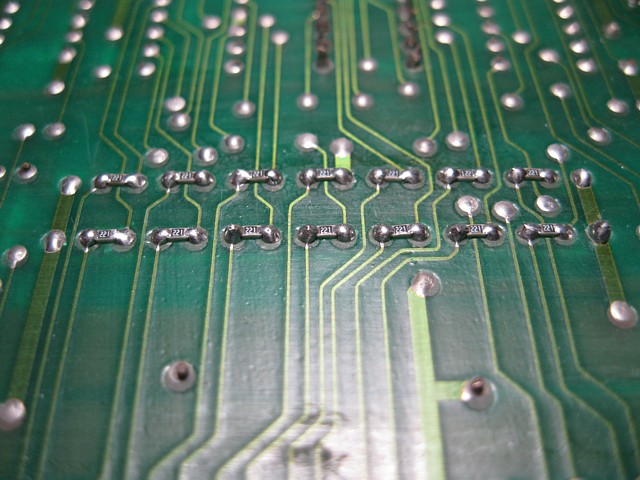
... with the series resistors replaced by surface mount types placed on the 'solder side'. I selected 0603 package resistors which neatly span between the existing PCB pads while still allowing the through-hole pullup resistors to be installed.
Having replaced the messy and damaged resistor networks which were previously fitted to the first of my two Exerion PCBs it now looks complete and intact enough to power on and test.
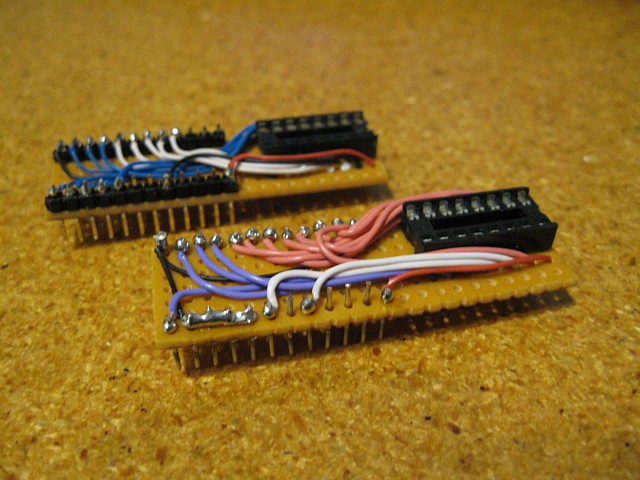
As with all of my pre-JAMMA board repairs to date I've made up a new test lead specifically for the unique pinout of this game PCB. Initially just comprising power, video and speaker connections it will eventually include control inputs when required to allow all board functions to be fully checked.
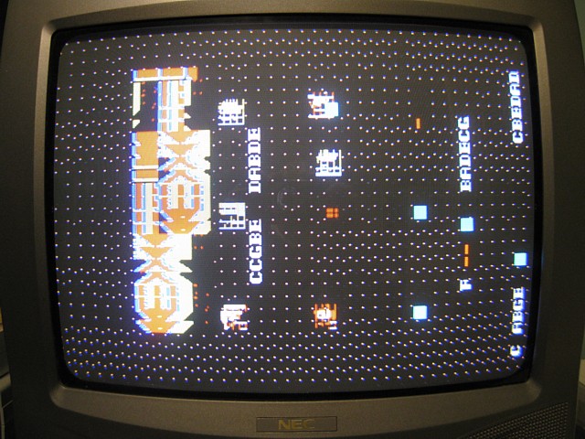
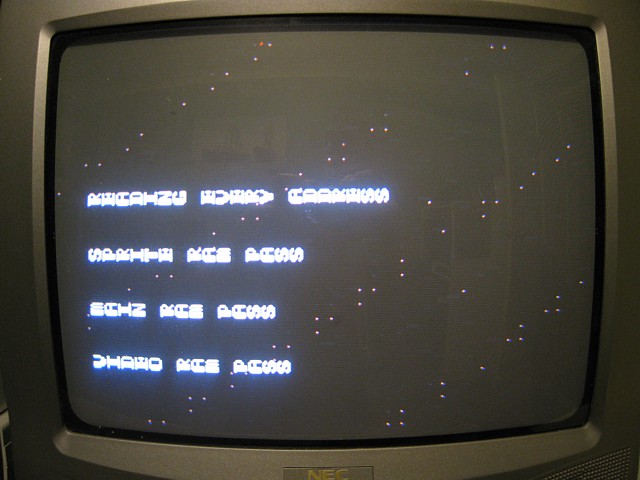
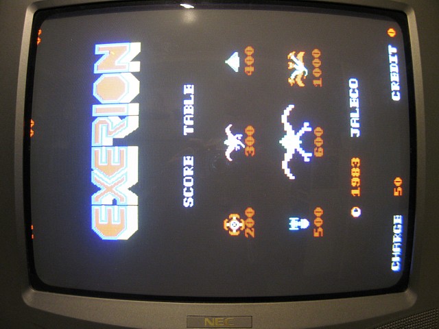
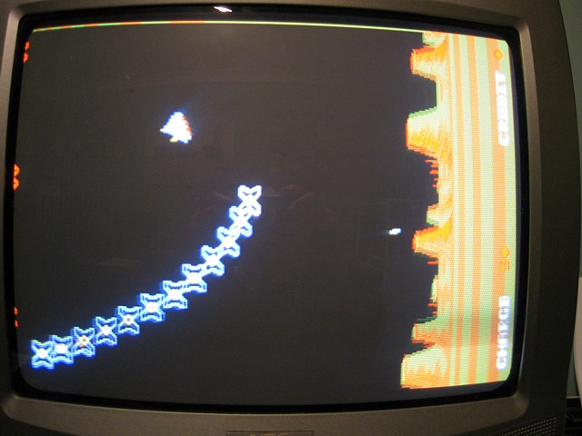
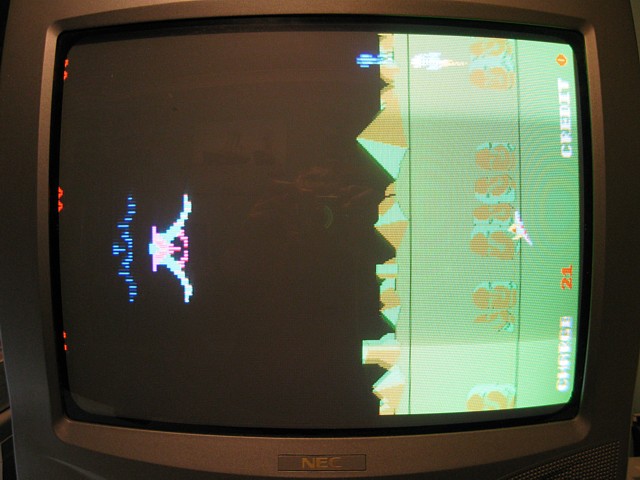
Powering it on we get this display. It's a good start, there is sync, some characters correctly displayed though the background is wrong and the numbers are not displayed correctly. Using a wire link to add a credit does change the appearance of the character which should be the number of credits though, so at least 1 of the 2 CPUs is running and responding to inputs.
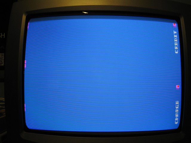
There's no attract mode being displayed and Player 1 / 2 Start seem to have no effect, there is no sound to be heard either. So it looks like a pretty major fault, or multiple faults. There's no service or test input on the PCB edge connector so I don't think there are any diagnostics available to assist. On that note, I think we should start by reading and verifying the EPROMs.
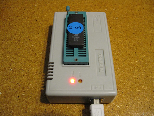
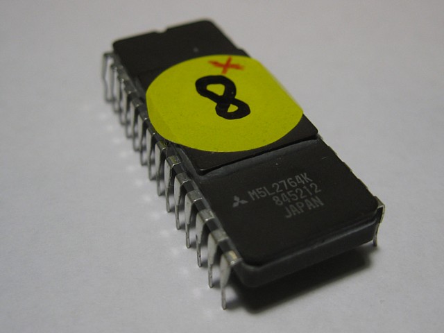
The EPROMs have some labels, the first two are illegible followed by numbers 3 to 7 and the last two have no labels at all so I'll stick with the sequence and number them 1 through to 9 initially. Referring to the MAME driver for Exerion will help to verify the EPROMS as all 'known' sets are listed within, along with their checksum values.
The first EPROM reads and verifies OK and matches the checksum for exerion.03 in the MAME listing. The second reads differently each time, unable to verify against its own previous read so that IC is faulty. Borrowing the same ROM from my 'backup' PCB for the moment, that one reads and verifies OK and its checksum matches with exerion.04
Having replaced that EPROM, I retest the PCB but find no noticable difference at this stage. Nonetheless the IC was faulty and needed replacement, along with whatever other faults still remain. Continuing with the reading and verifying, when I remove EPROM number 8 from its socket, I find one pin was bent and hadn't been inserted correctly.
Carefully straightening the pin, the IC read and verified OK and its checksum matched exerion.06 (GFX 1, foreground characters). I've reinserted the EPROM into its socket making sure the straightened pin remained intact. The equivalent ROM was missing from my 'backup' PCB but no matter, having read and verified this one successfully I can always program new replacements as required.
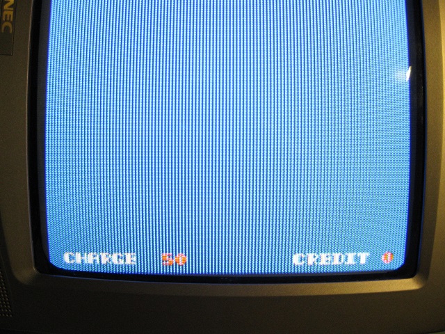
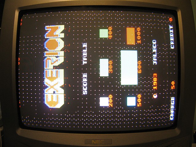
Re-testing the PCB the numbers now display correctly but there is no improvement to the background or other activity. This was obviously a secondary fault caused by someone attempting to troubleshoot the main problem. With all the EPROMS read and verified it's time to move on.
As this PCB has two Z80 CPUs I'd like to know which functions are controlled by each, to assist with fault tracing. I can learn a lot about the hardware specific to this PCB by observing the way the Exerion firmware is handled within MAME and will try a little experiment.
Starting with the complete, working firmware set, I'll substitute a 'blank' rom file for each of the EPROMs in turn and note the effect. This should at least reveal the main functions performed within each section of the hardware.
Each time I'll be running the mame executable file from a command prompt, to avoid using the MAME User Interface, which prevents the running of non-matching ROM files.
So, EPROMs 1 to 4 which are noted as bg-data, when 'blanked' cause the loss of terrain and cloud details strip by strip until the ground appears just as plain coloured stripes scrolling down the bottom of screen.
EPROMs 5 and 6 are the program ROMS for the main CPU and removing either crashes the program. When EPROM 5 is 'blanked' there is just a screen full of red numeral 6s, 'blanking' EPROM 6 causes some sort of reset loop. The exact symptoms on actual hardware may differ but it is clear the main program runs on this CPU / ROM and RAM section.
Interestingly, EPROM 7 being the program ROM for the second CPU causes the loss of all background and scrolling when 'blanked' but does not affect game play, at least not within MAME anyway. So it seems the function of this whole section is to provide the scrolling background though it must interact with the main CPU as the player's input affects the parallax scrolling direction.
EPROMs 8 and 9 are the foreground characters and sprites respectively and 'blanking' them simply results in the loss of these images, replaced by blocky 'holes' in the overall game screen.
Getting back to the actual hardware on my first Exerion PCB, I'm initially concentrating on the main CPU and its supporting components. The Z80 CPU itself is not socketed but its associated 6116 Static RAM memory is, having probably been replaced at some stage. I don't have any spare 6116 ICs at the moment and its counterpart on the secondary CPU is not socketed so I don't have the simple option of swapping the memory ICs.
I can however remove the IC from its socket and see if it makes any difference. Sure enough, powering the PCB up with no RAM memory installed in that position gives me this:
It's nice to see that removing the component has had the expected outcome of creating an additional fault. That's just about as good as confirming that the memory chip is OK Isn't it?
Maybe not! - I've recently purchased an inexpensive EPROM programmer to handle larger capacity EPROMS than my Dick-Smith-Kit programmer can manage, such as the later revision Boot-ROM for my Golden Tee Fore PCB. In addition to the wide range of devices which can be programmed its ability to test some logic and RAM memory components is a bonus.
To familiarise myself with this feature I've been placing various components in the socket and testing them. Checking the 6116 and expecting a 'Pass' I'm surprised when it reports a fault. Apparently there is an address line problem which, depending what address lines are affected could result in large chunks of memory not working while other ranges remain unaffected.
On that note I've ordered some new 6116 ICs and will replace this one before proceeding any further.
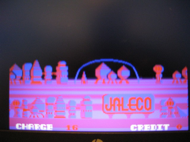
So, putting the PCB aside (again) while awaiting parts, I'd like to try another little experiment with the EPROM files, in MAME. I've seen how the contents of each EPROM contribute to the overall game graphics and wonder how the background images are formatted. There's a little detail which has been included in one of the planetary skylines, a 'billboard' with the game maker's name, JALECO on it -
Just to see if it can be done, I'll try to edit that. There appear to be four colours in the background image so it will be 2 bits per pixel but I understand from the details in the MAME driver that some of the data bits may be swapped on the game PCB - so the contents of the EPROM might also be swapped accordingly.
That would make it really difficult to open and edit the image without first transcoding all of the data. Fortunately it's just a small segment which I wish to edit and can be done by trial and error, changing a pixel at a time and observing the effect. Eventually I have found and altered the required pixels to effect this change:-
So there you go, my own personalised copy of Exerion. I probably won't go the extra step of committing those changes to the actual game EPROMs as I'm more interested in originality but I'm sure it would work equally well on the real game PCB.
I've been waiting on some 'new' 6116 static RAM ICs to replace one on my Exerion PCB which failed a test using my new Eprom Programmer's RAM checking feature. My order has now arrived and after double checking the new ICs pass the same test I've placed one into position 4N on my PCB which was already socketed.
Not entirely unexpectedly, having replaced the RAM the symptoms are exactly the same. That's not to say that IC was OK all along, just that there are other issues which still need to be addressed.
I'm reluctant to desolder components which aren't socketed just to test them so would prefer to diagnose the system in-situ. To make this process a bit easier it's back to my (limited) experience writing simple assembly language programs for the Z80 processor.
The Exerion ROMset appears to have no test or diagnostic routines whatsoever. There doesn't appear to be any watchdog timer on the PCB either which makes programming new routines a bit easier at least. It seems like a good idea to start with a simple RAM test, provided I can find a way to make the result visible (or audible).
Referring to the memory mapping for Exerion (thanks as always go to the MAME Dev. team for such a valuable resource) there are 3 blocks of RAM memory for the Main CPU being the Main RAM, Video RAM (both 6116s) and 1kByte of Sprite RAM being a pair of 2114 1k x 4bit static RAM ICs.
Beginning with a minimal assembly program - to put some bytes into Video RAM - and substituting the resulting assembly for the 'boot' ROM (Prom5) then running the ROMset in MAME I can see the resulting blocks on the screen. Progress, great!
So, by trial and error with each program revision I have worked out the screen mapping and found that the on screen text (seen during attract mode) is ASCII based, even better! This means I can use the existing character set to display messages on the screen (provided that hardware is functional, of course).
And if the text is not displayed correctly, that in itself could provide a useful clue to the hardware problems on this PCB.
My Revision 1 RAM test simply fills each block of RAM with a byte of data and (when each block is filled) goes back and reads the data back from every location, checking for a mismatch. If there are no errors it repeats, using every data value from 0 to 255.
I've started with the Video RAM as this causes the screen to be overwritten, beginning with data 21 (Hex) and finishing with 20 (Hex). If all goes well this leaves the screen blank as 20 Hex is the ASCII space character, saving the need for an additional program loop to clear the screen.
The results can then be written to the screen, followed by the main RAM test and Sprite RAM test results. Because of Exerion's vertical screen orientation, consecutive characters display in a column i.e. 'down' crossword style rather than 'across'. Although it's possible to display the text in rows the extra math required is not justified for a simple diagnostic program so I leave it that way.
After the RAM tests have completed, pass or fail the program enters an endless loop where the CPU reads every possible address, placing the result in one character block on the screen to show continued activity. In the past I've found this a really useful way to produce predictable waveforms on the address and data lines, address decoder select lines etc. for troubleshooting with an oscilloscope so I've included that here.
And finally, testing the program (still in MAME) I get this-:
Triffic! All that time spent programming video games to run on my Ohio Superboard when I was supposed to be studying for my HSC wasn't wasted after all..
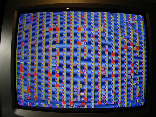
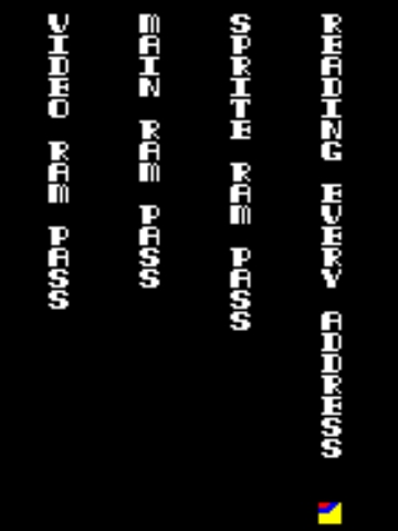
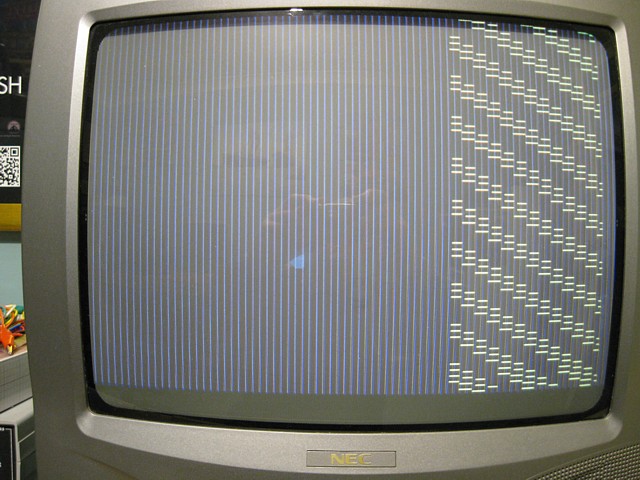
Anyway, burning the program onto an EPROM and installing it in place of Prom5 on the PCB gives me a really interesting result; The image is pretty jumbled and the blue 'venetian blind' background is still there (obviously a hardware problem, that) but I can make out the word 'PASS' and not 'Fail' for all three RAM tests. The reading address loop then continues to run, as planned but with a bit of screen flickering, another possible clue.
After this initial success, it occurs to me that my Rev. 1 RAM test is flawed - by placing the same data in every location I'm not checking for addressing issues; say there is an address conflict and some of the data is written to the wrong address. A single address may be overwritten while other locations are not accessed at all. When reading back the same address may be read multiple times but as the expected data is the same no error is detected.
To try and detect this potential error I'm adding another loop for each block of RAM, writing the address of each memory location as data then returning to read every address back, comparing the data read to the address. As the address is a 16 bit word there are two passes, one for the high order byte and another for the low order byte. Any memory location accessed incorrectly or overwritten should show when the same address is read back.
This adds 4 new loops for each bank of RAM (2 write and 2 read) and those with a little programming knowledge are probably asking 'why not use a subroutine for these read / write loops?' My answer is;
1/ I'm too lazy to put all the necessary parameters into registers each time the subroutine would need to run and there are limited registers available in the Z80 anyway.
2/ I don't need to make this tiny program more compact and find it easier to visualise the program flow without jumping back to a subroutine and, very importantly;
3/ each time a subroutine is called the Z80 places the return address on the stack - a location in RAM determined by the Stack Pointer. If that RAM address is unreliable or overwritten by the program accessing that location directly the program will fail.
I suppose you could exempt those few bytes of RAM from the testing routine but avoiding a subroutine or 'pushing' data onto the stack ensures the program will run without depending upon the integrity of the RAM.
And so, having added all these extra checks and re-tested it in MAME I've burned RAM Test Rev. 2 onto the EPROM and have a new result!
In this photo you can see how jumbled the image is but it's still possible to see the result of the RAM tests now says SPRITE RAM FAIL where the previous version said PASS so there must be some sort of addressing issue with the Sprite RAM but not the Main or Video RAMs, which still say PASS.
This has given me lots of clues to work on, checking the addressing of the Sprite RAMs and the 2114 ICs themselves, looking into that blue background etc.
To help troubleshoot my Exerion PCB I've written a little diagnostic program which begins with a simple memory test. My second revision which also checks for memory addressing issues found such a problem in the area of the Sprite RAM.
To shed some light on the issue I added a routine to display the address of the offending result in binary and the data read from that location which seems to confirm that addresses in the Sprite RAM region were being incorrectly overwritten during the test sequence.
It turns out however that result was a bit of a Furphy - although the Sprite RAM totals 1kByte (2 x 2114 1k x 4bit Static RAM ICs), referring to the circuit diagram it seems their upper 3 address inputs are linked to ground, reducing the addressable region to only 128 Bytes.
So, revising my program again to correct the memory range tested the RAM tests now all PASS. Having verified all the ROMs and tested all the RAM, at least for the Main CPU it's time to move on to some of the other clues.
Looking for the cause of that ever-present blue 'venetian blind' background, starting at the video output from IC location 1E the offending signal can be traced back via ICs at 2D and 9A to the output of 11A, another RAM IC in a group of 8, each one being 1k x 1 bit. This additional area of RAM is not directly accessed by the CPU but appears to be a sort of sprite buffer.
The output of the RAM is stuck somewhere between correct logic levels and it's the only one of the 8 in its group which is socketed, having been previously replaced. This seems suspicious and probing around the 74LS298 latch which follows I believe that IC may be the cause of the problem, the RAM possibly failing more than once due to excessive loading on its output.
I'm ordering some 74LS298s as well as a couple D2125 RAM ICs and will have to wait for those to arrive, meanwhile removing the RAM from its socket and temporarily linking its output pin 7 to ground the blue background disappears. Refitting the original program EPROMs, a normal looking attract mode appears at last.
The only obvious problem remaining is alternate pixels of the sprites are missing which will hopefully be corrected once those 2 ICs are replaced. Using a wire link to add a credit and selecting one player start, the game runs correctly but there is still no sound from the speaker.
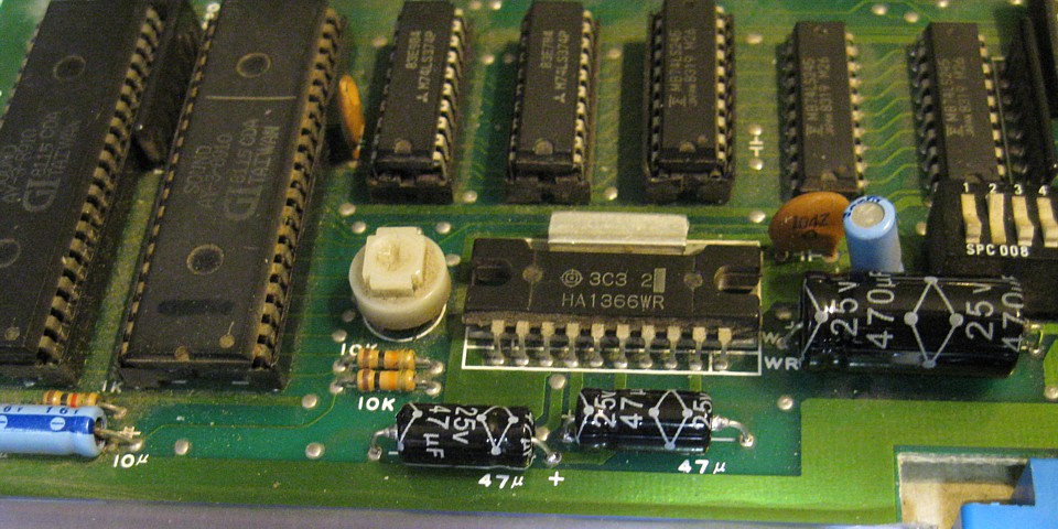
The sounds are produced by two AY-3-8910 programmable sound generators, the outputs of which are mixed together by a pair of 10k resistors followed by the Volume pot. then amplified by the HA1366 IC, powered by the +12V rail. Probing along that route it's a relief to find the sounds are present up to the input of the amplifier IC which does have power and appears to have failed.
I've ordered a replacement IC, meanwhile connecting that mixed signal to my RGB-modded NEC TVs audio input using a clip lead allows me to test the game operation with sound. I'm keeping this PCB as original as possible and the Autorec cabinet I plan to install it into only has a single speaker but it occurs to me that the output of the two sound generators could be separated and drive a stereo amplified cabinet with interesting effect.
And with the game now running I've added control inputs to my test harness, once again using a pair of DB9 connectors to suit my 2 button Quickshot joystick. In 'upright' mode only the player 1 controls are active for both while in 'cocktail' mode (set by Dip Switch 1 position 8 being Off) both sets of control inputs are used. I haven't added switches for coin or start buttons, these can be easily applied using a wire link.
My first Exerion PCB is now running and I'm awaiting some ICs which will hopefully correct its remaining issues with the sprites and sound.
In the meantime I'll do a bit of tidying up on both PCBs, fitting some new parts which I ordered earlier before turning my attention to troubleshooting the second PCB.
There are a number of electolytic capacitors, all located near the 'connector' end of the PCBs which were showing some damage from rough handling, both boards having been purchased as non-working and stored in less than ideal conditions.
I've already replaced some of them and as a precaution I'll do the rest. There are 10 on each board, ranging from 2.2uF to 470uF with the larger ones being 'axial' while the smaller ones are 'radial' but installed laying horizontally on the PCB to reduce the risk of physical damage.
Having done that I'm also replacing the crystals. The correct crystal frequency for Exerion is a readily available 20MHz but my first PCB had a much rarer 19.968MHz crystal installed. Although close enough to work without any noticeable difference that happens to be the correct frequency for Space Invaders so it will make a useful spare.
My second PCB had an 18MHz crystal installed which, at -10% compared to the correct frequency is stretching the friendship a bit. For optimum results I'm fitting shiny new 20MHz crystals to both boards.
I've also noticed a number of damaged ceramic capacitors on both PCBs. These are mostly 0.1uF 50V, scattered around the PCB to filter high frequency noise from the voltage rails. Some have been bent over with leads broken and some gouged or chipped. I have a handful of spares and am replacing any which are damaged such as these...
Now putting my first Exerion PCB aside while I await parts which will hopefully complete its repair, I'm getting the second PCB ready to power on and test.
Once again I've read and verified all the EPROMs and programmed new replacements for the faulty and missing ones. I've pre-tested and installed two new 6116 RAM ICs for the Main CPU as these were also missing.
A 74LS169 IC was missing from position A12 on the board so I've replaced it, installing a new socket. I've also noticed a PROM in position L8 which is socketed, presumably having been removed and tested or replaced at some stage.
The PROM is 256 x 4 bits (1kbit) in a 16 pin package so, making up a little adaptor to convert its 8 address lines, 4 data and 2 enable as well as +5V and ground, to match the equivalent pins of a 2716 EPROM, I can verify its contents using my old EPROM programmer.
It's similar to an adaptor I made to verify a PROM on my Missile Command PCB but that one was 32 x 8 (32bytes). In this case I've linked the unused upper 4 data bits of the 2716 pinout to ground and will be reading 256 bytes of data but the upper 'nibble' will always be zero.
Having done all that the contents of the PROM match the checksum of the equivalent ROM file in MAME so the PROM is OK, phew! Placing it back in position and firing the PCB up this is the initial result:-
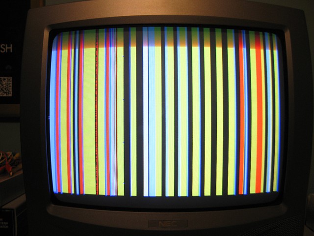
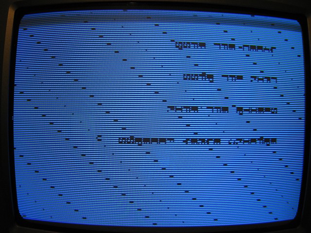
Well, it's colourful... The image is stationary so there's sync but no activity apart from a bit of glitching on the image here and there. There's no sound or response to inputs either. So much for the game program, what about my home brew test ROM?
This gives me a bit more to work with. Apart from the faint lines, sometimes there are attempts to display characters but these are unstable and 'rolling' vertically on my monitor. There's also a cyclic glitching noise from the speaker which gives me the impression that the program is running, has failed out of the RAM tests almost instantly and advanced to the 'reading every address' endless loop.
The test program should continue even if the RAM has failed and the two 6116 ICs were tested before installing so if the test did fail there must be an issue with the support logic rather than the RAM itself. If the program is still running the CPU must be working and able to read the test program EPROM, at least.
Checking the power rails, clock and other signals around the main Z80 CPU, it's apparent that the test program is running with all the address lines busy as well as the /MREQ control signal. Looking at the data lines however there's an obvious issue :
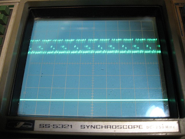
There's some half-height pulses on the data lines which are not valid logic levels and must be originating from one of the devices connected to the data bus. The data lines from the CPU are connected directly to its two program EPROMs as well as the main RAM followed by a 74LS245 bi-directional buffer which carries data to and from other parts of the circuit.
Comparing one of the affected data signals with the select line for the data buffer (in location 2P on the PCB) the timing of the buffer's select line appears to coincide with the data having the incorrect levels. That 74LS245 will need to be replaced, unfortunately I don't have any new ones in stock at the moment.
I'll order some, meanwhile I'm reluctant to borrow parts from my other PCB which is already running but I might have a socketed one on a not yet repaired board which I could try, if I'm lucky.
I've been working on my second Exerion PCB and found an issue with invalid signal levels on the main CPU's Data Bus, apparently coinciding with a 74LS245 buffer being selected. I couldn't find a 'spare' buffer IC to use for testing, fortunately my order for some new replacements arrived without delay.
Having fitted the new component however the fault remained. So, if the buffer itself was not responsible for the low level data signals the next most likely cause would be a Bus conflict, perhaps two devices were selected to output data at the same time due to an address decoder issue.
It's always fascinating to see how the CPU address range is divided into blocks and select signals created in the logic circuits surrounding the CPU. In this case the lower half of the available address range is allocated to the ROM and RAM which is directly connected to the CPU data bus while the upper addresses are used for the more distant Video and Sprite RAM and Input / Output interfaces.
The first half of the 74LS139 in position 3R decodes these lower addresses, providing a low going select signal for each 8k address range. As the first program EPROM is a 16k 27128 however the first two select signals are then combined by the 74LS08 AND gate at position 7T. Its output appeared to be stuck low, leaving PROM 5 permanently selected. Replacing the 74LS08 cured that.
Although the screen was still pretty blank there was now a significant pause before the cyclic noise from the speaker commenced, suggesting one of the RAM tests was completing before moving on to the 'reading every address' loop. Sure enough, the signals around the main RAM now appeared to be active for the approx. 13 seconds duration of its RAM test.
The Video RAM wasn't noticeably active however suggesting that test failed almost immediately and the program had moved on. Checking the signals around the Video RAM something immediately seemed amiss.
The Address and Data lines to and from the Video RAM are switched between the CPU busses and an output circuit which reads the data and generates the foreground video to be displayed. During this readout the addresses are driven by a series of counters and some of these signals were missing. Replacing the 74LS161 counter at location 8H corrects that missing address activity.
Although this doesn't solve the Video RAM errors from the CPU side it does provide us with a meaningful Video output at least. Refitting the original program EPROM we now have this display:-
There's soooo many issues with this image and no sound to speak of either but it is running the attract mode and even starts a game when 'coined up', fantastic! I'll keep chipping away at the remaining problems, top of the list are those Video RAM errors.
Switching back to the latest revision of my home brew test ROM (Revision 6 now initialises the video register to ensure the RAM test results are displayed correctly using actual hardware) and viewing the signals around the Video RAM using an oscilloscope, the Address lines seem OK but the Data signals have invalid levels just like the previous Main RAM problem.
Asm316.asm RAM Test Rev.6 Assembly listing
Prom5_diags6.4p RAM Test Rev.6 Hex file
Apart from the 6116 RAM IC which has already been tested, those data lines are only connected directly to another 74LS245 bi directional buffer as well as the inputs of a 74LS374 single direction buffer. Some of the data levels seem OK while some are invalid so the most likely cause seems to be the 74LS245 which could be affecting the data in one direction only.
The IC in question, in location 2N on the PCB was manufactured by Fujitsu, such components have a notoriously high failure rate so I'll take a punt and replace it, also installing a socket. That done, the RAM tests now all PASS. It's fortunate that I bought those new 74LS245s after all...
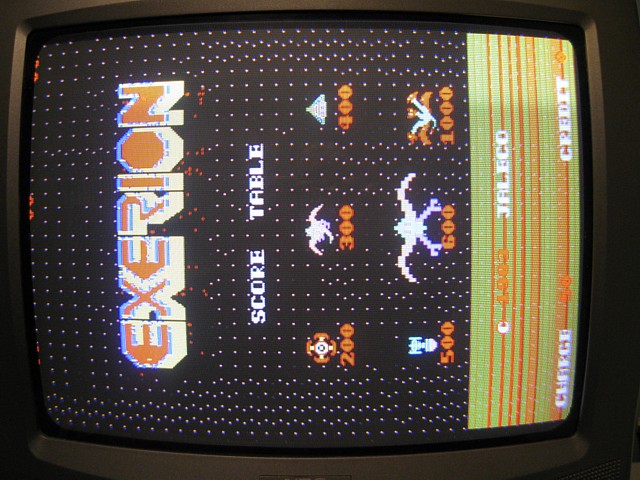
So, how's the game display looking now? Coming along, foreground characters are displaying correctly but there are spurious dots on the screen which appear to be on the same layer as they are not present during gameplay, only in attract mode.
There are also obvious issues with the sprites and apparently no backgrounds or sounds. Where to begin? Let's work on those sprites next.
The 2 x 2114 sprite RAMs which are accessed by the main CPU passed their RAM tests so appear to be OK. The sprite EPROM, in position 11L has been verified so is also OK but the signals around it haven't been checked.
Viewing the Voltages and signals on each pin of the EPROM using an oscilloscope, the incoming address lines appear OK however the data outputs are not going fully low, having a minimum level of about 1 Volt.
Working along each pin the cause of the problem becomes apparent. The ground pin (14) is also sitting at about 1 Volt. Investigating the cause of the poor ground it initially seems a dry joint may be responsible.
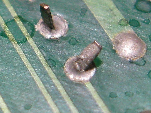
In this close up we can see the ground pin which has been bent over at some point and the solder joint appears fractured. After resoldering however there still appears to be a high resistance (about 7 Ohms or so) between ground on the PCB and pin 14 of the EPROM. So, the best bet is to replace the socket. That done, the sprites now appear correctly.
In this photo we can also see the background layer, which has been completely absent most of the time, has mysteriously appeared - it isn't scrolling, it's not displaying any of the terrain details and it's not supposed to show up on this screen anyway. At least that does indicate some activity from the second CPU and its associated components, if only intermittently.
There's still a number of issues with the hardware around the main CPU however so I'd prefer to keep working on those and leave troubleshooting the background processing for later. Lets see if we can sort out those dots.
The contents of the Video RAM in location 6N are latched through to the address inputs of the Foreground Character EPROM in location 6K. This functions as a character generator, a sort of lookup table which converts character data on its address inputs to pixel data on its outputs. This in turn is latched through to a 74LS153 Multiplexer at location 8K which converts the 8 bit data to a sequence of 4 x 2 bit values. These are fed to the address inputs of the character palette PROM in location 8L, which I have already verified as working.
If there was some sort of data error prior to the character EPROM we would expect wrong characters to be selected however the characters are correct while some individual pixels are wrong, indicating the problem is in the area from the character EPROM to the palette PROM.
Using the oscilloscope, it's possible to observe the 'dots' which appear on the screen as brief pulses in the signals on the output of the multiplexer but I can't identify them in any of the input waveforms.The 74LS153 is not socketed and its pins look a bit rusty so I'd rather just replace it than remove, test and resolder it anyway.
After replacing the multiplexer the fault is still present but I'm happy to have installed a new IC and socket for the sake of reliability. So the fault must be before the multiplexer, casting suspicion on the latch or the EPROM itself.
This particular EPROM was missing from the PCB so I had programmed and installed a replacement from my ancient hoard of spares. Although the data verified successfully at the time it could be this IC is simply too slow to respond at pixel clock speed. The access time specification for this part number is apparently 250 nanoseconds though it's not printed on the IC itself.
In any case, finding and programming a slightly newer 27C64 with a 200 nanosecond access time solves the problem and the 'dots' have disappeared.
It's even possible to play the game, albeit with no scrolling background and no sounds other than a few buzzing noises. Time to work on the sound.
My two Exerion Arcade PCB repairs have been progressing slowly, I've been sorting an issue at a time and putting one PCB aside while awaiting parts, to work on the other. Both are now running and able to play a game, while I await parts for the sound amplifier and sprite issues on the first PCB I'm chasing down the remaining faults on the second, being the sounds and the scrolling background which is completely missing most of the time.
Looking into the sounds now, there's an obvious issue which I knew about but haven't attempted to resolve until the game was running and the sounds able to be tested properly.
This looks like a 'quick fix' repair, probably done at the time to resolve a socket issue and get the PCB back onsite without delay. The two AY-3-8910 Programmable Sound Generators were presumably removed from their sockets and soldered directly onto the PCB pads without replacing the socket or even clearing the through holes on the PCB.
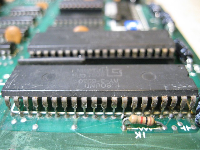
It may have worked at the time but with years of dirt, corrosion and poor handling the minimal contact between pin and pad has eroded and a number of the connections are bad when tested with a multimeter. Carefully desoldering the pads and removing the two ICs, the PCB appears undamaged.
Cleaning the IC legs and refitting, using new 40 pin sockets and testing, some of the sounds have returned already but some of the sound 'components' are still missing. The sounds appear to be missing a 'noise' component, the shots and explosions sounding like musical notes without any 'hash' or 'rumble' added.
Now that both ICs are socketed, a simple check is to swap them and see if the symptoms change. Having done that the sound is slightly different (indicating at least one IC must be faulty) but there is still the lack of 'noise', just a slight glitching added to the sound effects.
So, what conclusion to draw from that? The two ICs give different results so at least one is faulty. The same sound component is lacking in both cases so either the second IC is also faulty or there is an additional fault on the PCB somewhere. Maybe the two ICs were originally at fault and removing their sockets at the time didn't resolve the issue...
This is the point where I would normally put a repair aside and order some replacement ICs but rummaging through a box of 'future projects' I find a Pooyan PCB in unknown condition, bought as part of a job lot which uses a pair of the same sound ICs. They're both socketed and pretty original looking with 1982 date codes. I'll 'borrow' them from the Pooyan board and give them a try.
Success! Having replaced both ICs the sounds all seem to be present and correct. I'll order a couple of replacement ICs for the Pooyan PCB and put the two original ones from this board aside, marking them as faulty. At some point I may find or write a test routine to confirm if both have failed but don't wish to waste any more time on the sounds now, it's time to move on to that missing background.
There's a big difference between repairing Arcade Game PCBs as a hobby and doing so on a commercial basis. In their day the profitable life of a game was often measured in months, not years and any downtime during that period was costly. If a fault developed which was difficult or time consuming to repair the game would probably have been replaced outright.
Now these ex-arcade games are 'retired' and mostly in the hands of collectors there is not quite so much urgency to return a faulty game board to service. As they become more sought after, PCBs which would once have been discarded are now worth spending the time to repair. Unfortunately with many of the components becoming obsolete, scarce and sometimes unobtainable there are new factors which affect the commercial viability of repairing.
With a great deal of patience however many game PCBs which were previously sidelined can still be rescued and revived. The two Exerion PCBs I've been working on for many months, punctuated by long pauses while awaiting parts, are now both on the home stretch and look like being completely repairable.
My second or 'backup' PCB has now overtaken the first and is working apart from the scrolling backgrounds which actually have no effect on gameplay. Let's see if we can get them up and running to complete this repair.
The backgrounds are generated in a separate section of the circuit, controlled by the second CPU with its own program EPROM and RAM as well as the background graphics data contained in a bank of four EPROMs. Control of the background and scrolling is via a 74LS374 latch in position 2S which receives signals from the main CPU and is then read by the second CPU running its own program.
I've seen some intermittent background activity so the problem is likely to be a marginal component which works to some extent, occasionally. The second Z80 CPU and its associated 6116 RAM are not socketed and have not been tested but the program EPROM is a replacement which I've programmed and verified as the original was missing.
Beginning with a look at the signals around the CPU the +5V supply, ground and clock signals look OK. The CPU appears to be attempting to read from EPROM with the memory request /MREQ signal active as well as the lower address lines. Looking at the outputs of the address decoder the program EPROM is the only selected device as the higher address lines are currently inactive.
This isn't necessarily a problem with the address decoding, merely an indication that the program is not advancing beyond its initial stages, attempting to read from EPROM. The data signals from the EPROM reaching the CPU are more of a concern, a couple of the data bits are not active. Taking a step back and retesting the EPROM, I find that it no longer verifies correctly with the program file.
Erasing and reprogramming gives the same result so this EPROM is another dud. I'm fast running out of spares but have some newer ones on order which will hopefully arrive soon. Meanwhile, finding one more good 27C64, programming and installing it gets the background program running.
There's still a couple of problems to solve, some of the strips which are meant to contain scenery appear blank also the ground terrain looks wrong, showing as lines instead of the expected strips of varying depth. Both symptoms are most likely caused by more EPROM and / or socket failures, this time in the bank of four BG-Data 2764 EPROMS.
More measurements - and there's an obvious problem with the first EPROM checked, the +5V supply is not reaching pin 28 of the IC. This turns out to be another socket with poor contacts and replacing it brings back the missing terrain, still with some errors though as there are lines through the images. For the sake of symmetry and to see if it makes any difference to the missing ground terrain, I'm also replacing the other 3 EPROM sockets in this bank.
The new sockets should be more reliable long term but as it turns out, don't solve the present issues. Looking at the signals around the four BG-data EPROMS they all seem to be active now so looking further, each EPROM is followed by a 74LS374 buffer and the outputs of two of those look wrong. Fujitsu ICs again, in locations 5A and 5H. Replacing them, adding sockets gets the background terrain and scenery working.
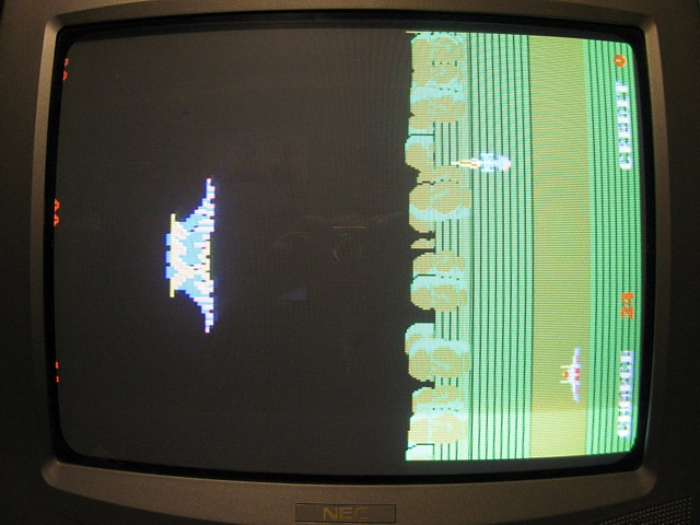
Now we're really close, the game is running with sound, sprites and background all present. There's one last issue which I've just noticed and it's a bit of a 'glitch' so I'm expecting lots of trouble finding it. Even getting a photo of the problem on screen is tricky..
Can you see it? It only happens briefly, when the player's ship is fairly high up on screen the background terrain flashes up on the 'right hand side' of screen into the sky area. It's helpful in this case that the display is rotated, when viewed on a conventional monitor you can see this is actually the first line of active picture.
What's not good is the player's ship is a sprite, on a separate layer to the background so there should be no real interaction between them. The height of the player's ship does normally affect the height of the horizon as part of the parallax scrolling function but the problem only occurs on the first line of video after which the background is correct so I'm guessing some sort of noise or timing issue is causing it. Hmmmm...
So, to try and find the origin of the 'glitch' we need to start at the background video output and work back from there. To even see the offending output we'll need to use the delayed trigger function on the oscilloscope. Using the PCBs sync output as our first signal and triggering on that with High Frequency reject we can get a stable display with Vsync as our trigger point.
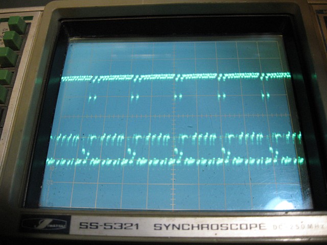
Now using one of the background video signals as our second trace and using the 'A trigger intensified' setting we can adjust the secondary timebase and trigger delay to highlight the first few lines of active video. switching to the 'B delayed' timebase and watching the background video while the PCB runs in attract mode we can see the occasional glitch on the first line of active video.
Using our third beam to probe the PCB now (the Iwatsu oscilloscope has a 3rd channel, very handy at times but alternatively we could have used an external trigger input and 2 channels) we can see any signals which coincide with the 'glitch' on the background video.
Working back from the outputs of the background layer at location 3L, the glitch appears to be present in previous stages at locations 4KJ, 4LK, 5J and seems to be originating in the 74LS74 flip flop at location 7J. Interestingly, a ceramic capacitor has been added from its input pin 2 to ground which isn't in the circuit diagram so appears to be an afterthought or modification.
I'm guessing our glitch is caused by a false triggering of this latch due to noise on the input or bad timing between the input and clock signal, the capacitor possibly having been added to suppress some noise on the input if the problem was a known issue. The input and clock signals look OK and the glitch is only occurring occasionally so none of the components are obviously faulty, perhaps a little out of tolerance. The only real option is to try replacements and see if the symptoms change.
Initially replacing the 74LS74, then the 74LS08 in position 7F which provides the clock signal and finally the 74LS04 in position 7C which drives the input to the latch, the 'glitch' problem is almost completely resolved. It's obviously a very marginal timing or noisy signal which I can't see on the oscilloscope. In fact even touching the probe to the input of the latch is enough to affect the symptoms.
I've tried removing the capacitor which had been placed across the input to ground, predictably the problem is more frequent without it. I'm reluctant to increase the value of the capacitor as this would cause additional loading on the output of the 74LS04 which drives it. Instead I'm substituting a 7404 inverter for the 74LS04. Although 'older' technology the 74 series have a higher output current capability, effectively a lower output impedance and should be able to drive the output signal with more noise immunity.
That works a treat! After extensive play - er... testing there's no sign of the 'glitch'. Another alternative, if that hadn't worked would have been a 74S04, the higher speed / current alternative to the 74LS series which I suspect would have also worked. Having done that and replacing over a dozen of the damaged 0.1uF noise suppression capacitors previously mentioned I'm calling this repair finished. fantastic!
Now to complete the repairs to the first PCB as parts have just arrived...
To be continued...
Out with the New, In with the Old
This isn't a restoration as such, more a project. It starts with a genuine '80s arcade machine which had been 'upgraded' with a multigame PCB and LCD monitor.
Not afraid to buck the trend, I decided to 'un-grade' it back to the way it would have been, more or less. It wasn't a dedicated machine, just a generic upright 'woodgrain' cabinet which would more likely be found in the corner of a Fish and Chip shop than a major arcade.
I've no idea what games it would have run over the years, even the marquee is generic, added by the last operator. I do know it has pre-JAMMA cabinet wiring and retains its original single player control panel with 8 way joystick and 2 buttons, leaf switches and all.
Based on that I found a couple of non working Exerion PCBs and finally have one fully repaired and ready to install with the second not far from being a good, fully working spare board. I've also sourced some old CRTs and chassis and sorted through them to find the best prospects to repair and install.
This is our starting point, the multigame board and LCD had been fitted in place of an original arcade game PCB and CRT monitor.
Trying the not quite finished Exerion PCB out for size - That's more like it!
I'm retaining the multigame PCB as a plug in alternative, relocating it into the 'bowels' of the machine. Those black cables in the foreground are for the LCD and will not be required once the CRT monitor is fitted.
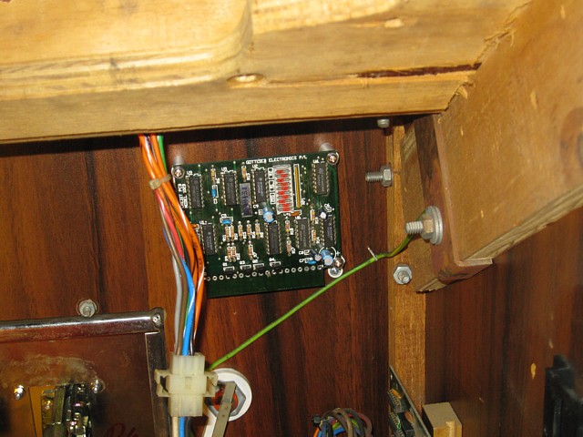
I had installed 10c and 20c coin mechs in this machine but the Exerion PCB only has a single coin input. Even though it's not used commercially I'd like it to function correctly so I'll eventually install this Gottlieb Triple Coin Credit PCB between the coin mechs and the game PCB to handle the two denominations.
After removing the LCD monitor the 51cm 20" CRT drops in and bolts up perfectly as the cabinet was built for this type of tube originally. The chassis mounts to the side panel in place of the original one which was still there but disconnected and incomplete.
The 100V transformer which powered the original monitor is still mounted in the base of the cabinet so I test it and wire it back in, adding a mains earth connection to the body of the two transformers and the arcade PSU.
The CRT looks good with no burned in image but could use some convergence adjustment when I get around to it. The factory adjustments are still sealed so it has never been readjusted. It could be the yoke has been bumped slightly out of alignment or the errors may have been there from new, these CRTs were never perfect.
The chassis is a Kortek, one of a few which I bought in unknown condition. When tested this one worked but with a very wobbly picture. After a clean up, several new capacitors and some adjustment it works well.
Having swapped the LCD monitor for the CRT and setting up to work with the multigame board it's time to make up a new adaptor from the cabinet wiring to the Exerion pinout. I've made it a bit longer than the JAMMA adaptor for the multigame board to allow the cables to be swapped without undue twisting of the cabinet wiring harness.
One of the most elusive parts to complete the conversion was the black plastic or, in this case fibreglass CRT mask which would have been surplus and probably discarded when the dead flat LCD monitor was installed. Fortunately I managed to source an original one whch was a nearly a perfect fit, just needing a couple of millimeters trimmed around the edges to fit the recess in the particle board surround.
 |
 |
On the left the CRT is fitted, with the original black painted particle board surround and glass, on the right the 'new' CRT mask is added and finishes it off nicely.
A few things left to do but it's together and running at least. After the time and effort getting all the parts ready I'm really happy with it, the period correct details add to the authentic feel of the machine. Even the games on the multi board look more 'correct' on the CRT instead of the LCD.
- and Exerion is my new favourite game!
Getting back to the first of two Exerion PCBs which I've been working on, having put this one aside while awaiting parts I've managed to complete the repairs to the second PCB.
Now the parts which I ordered have arrived I'm picking up where I left off and hope to finish this repair as well.
The only problems remaining were with the sprites and sound. The sound problem was very straightforward, a blown amplifier IC, Hitachi HA1366W.
There's actually two versions of this IC, the HA1366W and the HA1366WR which has the same specification but the pin connections are reversed. I suspect this was done to make the PCB layout easier for a stereo application which would require a pair of ICs, having one with the connections reversed would allow the two ICs to be easily laid out 'back to back' and potentially share a single heatsink.
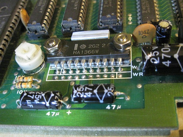
The Exerion PCB only requires a single IC, being mono but the PCB has both sets of connections to allow either variation to be installed. The original was a WR type but I found the W version more readily available at the time so that is what I've installed. Having done that the sound now blasts out from the single speaker.
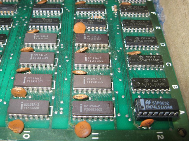
The main issue with the sprite layer was the entire screen was covered in a blue 'venetian blind' pattern where every second line was washed out with blue. This was caused by a faulty D2125 RAM memory IC which was already socketed, presumably having been replaced previously. As a precaution I also ordered some 74LS298 latches as this is the IC which follows the RAM, in case it was causing the RAM to fail due to excessive load on its output. The D2125 RAMs run pretty hot at the best of times and I didn't want to promptly blow up another one if the 74LS298 happened to be causing the failure all along.
In the meantime I removed the faulty RAM chip and linked its output pin 7 on the IC socket to ground to temporarily remove the blue stripes from the screen.
Having done that the image looked pretty good except every alternate pixel of the sprites was missing. At the time I assumed this was due to the missing RAM chip but actually there was a second fault;
There are 8 x D2125 (1k x 1 bit) RAM ICs arranged in two banks of 4, whose outputs are interleaved, alternate pixels of the sprites coming from each bank of RAM. For every second pixel to be completely missing an entire bank was not functioning, this turned out to be due to no signal on some of their address inputs, caused by a faulty 74LS169 in position 12A on the PCB. Coincidentally the same IC was missing from my other Exerion PCB so I had already bought some spares. Fitting a new one, installing a socket as well cured the missing pixels.
Now installing the new RAM in the existing socket, in position 11A causes an interesting effect:
This is not the world's worst convergence problem or a timing issue, it's actually an addressing problem. The data is being clocked into or out of the wrong address in RAM and therefore ending up in the wrong location on screen. It's not the entire bank of RAM either, just the 1 bit IC which I've replaced. Checking the address signals, sure enough one is missing but it's present on the rest of the ICs in that bank so it's either a socket issue or a damaged PCB trace.
Carefully desoldering and replacing the IC socket, there seemed to be some damage to the pads on the component side of the PCB when the original IC was removed and the old socket fitted so I'm doubtful all the connections on the top of the PCB will work once the new socket is soldered in place. As expected the same address input on pin 9 is still not connected so the safest cure is to add a wire link on the solder side, from pin 9 on the adjacent IC in the same bank of RAM. That fixes the fault and the PCB now appears to be fully working at last!
Incidentally, because these PCBs are so old, impossible to replace and have already had many repairs carried out in the past I'm extra careful not to damage any PCB pads or tracks when replacing components. If I know a component is faulty anyway I will remove it by cutting the pins then remove the pins and desolder the pads one at a time rather than desoldering and attempting to remove the component intact.
There's already a few links added on the solder side of the PCB to mend damaged tracks from previous repairs and though some are a bit messy they all look sound enough and everything works correctly so I think I'll leave well enough alone.
So now I have a fully working spare Exerion PCB which will come in handy if anything goes wrong with the other. Given the age of these boards there's no telling what else could go wrong or when...
This is just a little update to the Autorec arcade machine project, some minor repairs and finishing off some internal wiring, adding a few new features.
A little while back the machine started humming through the speaker and the image became a bit wavy. I suspected the power supply unit, the monitor chassis having already been re-capped recently.
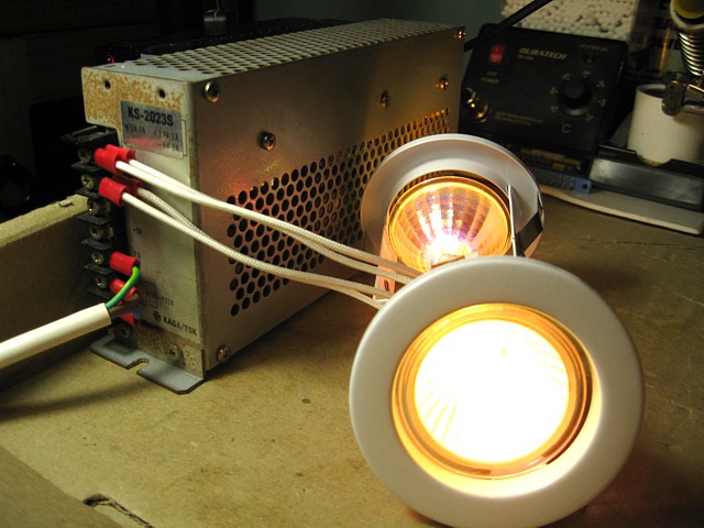
Temporarily substituting a known good power supply to correct the problem, the original Kaga power supply unit seemed worth fixing as it had not failed altogether but soon would if left unrepaired.
As the problem was a hum on the power supply rails rather than a high frequency noise the most likely cause would be the large capacitor which smooths the rectified AC near the (110V) input to the supply. Having removed the unit to repair on the bench it seemed worthwhile to order in a full set of electrolytic capacitors, using a higher temperature rating than the originals where possible.
After installing the new components the supply ran well on the bench using a couple of halogen lights for a load. The 12V 50W lamps are seen here running from the +5V rail so each was only drawing about 2.5A at this Voltage.
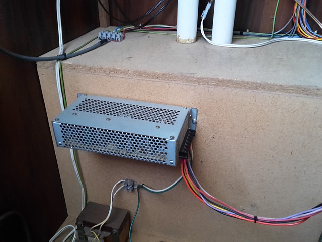
Returning the power supply to the machine I opted to mount it horizontally with the component side of the PCB facing upwards to allow heat to escape more readily as well as improving access to the internal Voltage adjustment pot. which can be operated by a trimmming tool through one of the holes in the perforated side panel. The power supply had previously been mounted at an angle with this side facing downwards for some unknown reason.
And so with the machine working well again with its 'original' power supply back in place it was time to complete some unfinished work on the machine wiring.
The multigame PCB previously fitted had no problem with two separate coin inputs but the Exerion PCB having only 1 coin input requires an external credit PCB to correctly handle two denominations, in this case 10c and 20c from the two Coin Controls roll-down type coin mechs.
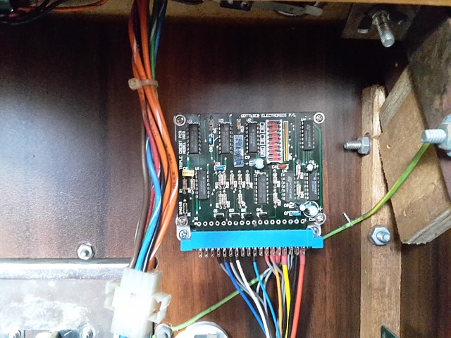
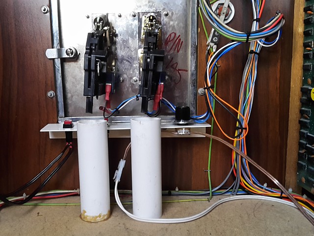
The original coin mechs were both set for 20c but were missing parts and not connected so I had replaced them, with one 10c mech and the other 20c. Although the machine is not used commercially it's nice to have all the components functioning correctly so I'd previously fitted a Gottlieb Electronics (Australia) triple coin credit PCB but not yet wired it in. It also has outputs to drive coin counters so I'll install a pair of those as well.
New wiring added to take the signals from two coin switches, driving the single coin input on the Exerion PCB as well as two coin counters. There is a Service switch input on the credit PCB which is directly connected to the coin output but instead I'll add a service switch to the third coin input allowing a number of credits to be set for each button press.
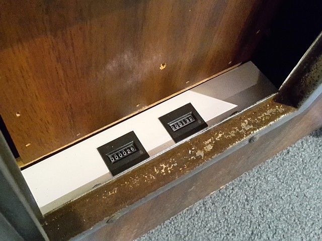
A little panel added inside the cash box door for the coin counters and another inside the coin door for the 'service' and 'test' switches. The test switch has no effect with the Exerion PCB, having no built in diagnostics but does work when the multigame PCB is plugged in via its Jamma adaptor. Dymo labels add a period-correct touch here.
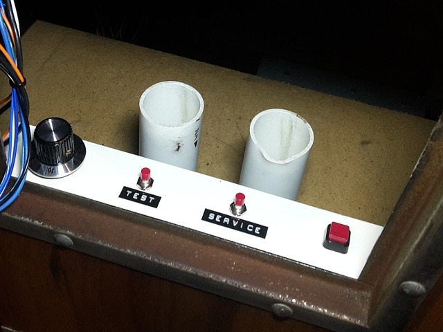
No test panel would be complete without Volume and manual monitor Degauss controls these have also been added. The degauss switch and volume potentiometer are wired in series with the degauss coil and the speaker, respectively. The Volume control is a 250 Ohm, 5W wire wound potentiometer which allows a good range of control without the sound ever being cut off completely.
Having placed a switch in line with the degauss coil, the monitor no longer automatically degausses each time the machine is powered on. This is fine as degaussing is only required periodically or if the machine has been moved, to correct any colour impurity on the CRT.
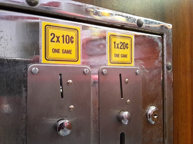
A couple of price labels to identify the 10c and 20c slots, the left hand coin mech being factory set for 10c coins has a smaller slot which helps to prevent that side being fed larger coins. The credit PCB has been set to output 1 credit for 2x coin 1, 1x Coin 2 or 5 credits for 1x coin3 (service switch).
Web Resources (External Links) -
former Autorec factory premises - Google Maps
Coin Controls S-1 Acceptor - the ARCade ARChive.
The Arcade Flyer Archive - Video Game Flyers: Exerion, Jaleco
All images and text on this website are Copyright.
Contact: jbtech at telstra dot com